Full catalog, 226 pages — browse the index or scroll the page.
We represent five Chinese company, they manufacturing rubber conveyor belt, they have different kind of belts and standard, RMA, DIN and others, according the countries and needs, we hope to be able to have one chance to have a contact and an opportunity of business with your company.
We have worked with conveyor belt more than fifteen years; help the manufacturer to selling annually more than ten million dollars in conveyor belts and rubbers products for Latin America.
We are defending the loyalty and trust, we have good reference with many companies, we are not trading, we are representing companies and we are consulting company too.
We are working also with Rubber Sheet, PVC Belt, V belt and transmission belts.
A conveyor belt is the carrying medium of a belt conveyor system (often shortened to belt conveyor). A belt conveyor system is one of many types of conveyor systems. A belt conveyor system consists of two or more pulleys (sometimes referred to as drums), with an endless loop of carrying medium—the conveyor belt—that rotates about them. One or both of the pulleys are powered, moving the belt and the material on the belt forward. The powered pulley is called the drive pulley while the unpowered pulley is called the idler pulley. There are two main industrial classes of belt conveyors; Those in general material handling such as those moving boxes along inside a factory and bulk material handling such as those used to transport large volumes of resources and agricultural materials, such as grain, salt, coal, ore, sand, overburden and more.
Today there are different types of conveyor belts that have been created for conveying different kinds of material available in PVC and rubber materials.
The belt consists of one or more layers of material. Many belts in general material handling have two layers. An under layer of material to provide linear strength and shape called a carcass and an over layer called the cover. The carcass is often a woven fabric having a warp & weft. The most common carcass materials are polyester, nylon and cotton. The cover is often various rubber or plastic compounds specified by use of the belt. Covers can be made from more exotic materials for unusual applications such as silicone for heat or gum rubber when traction is essential.
A conveyor belt can be a slide and be controlled by the force of gravity.
Material flowing over the belt may be weighed in transit using a belt weigher. Belts with regularly spaced partitions, known as elevator belts, are used for transporting loose materials up steep inclines. Belt Conveyors are used in self-unloading bulk freighters and in live bottom trucks. Belt conveyor technology is also used in conveyor transport such as moving sidewalks or escalators, as well as on many manufacturing assemblies' lines. Stores often have conveyor belts at the check-out counter to move shopping items. Ski areas also use conveyor belts to transport skiers up the hill.
Conveyors are durable and reliable components used in automated distribution and warehousing. In combination with computer controlled pallet handling equipment this allows for more efficient retail, wholesale, and manufacturing distribution. It is considered a labor saving system that allows large volumes to move rapidly through a process, allowing companies to ship or receive higher volumes with smaller storage space and with less labor expense.
Rubber conveyor belts are commonly used to convey items with irregular bottom surfaces, small items that would fall in between rollers (e.g. a sushi conveyor bar), or bags of product that would sag between rollers. Belt conveyors are generally fairly similar in construction consisting of a metal frame with rollers at either end of a flat metal bed. The belt is looped around each of the rollers and when one of the rollers is powered (by an electrical motor) the belting slides across the solid metal frame bed, moving the product. In heavy use applications the beds which the belting is pulled over are replaced with rollers. The rollers allow weight to be conveyed as they reduce the amount of friction generated from the heavier loading on the belting.
Belt conveyors can now be manufactured with curved sections which use tapered rollers and curved belting to convey products around a corner. These conveyor systems are commonly used in postal sorting offices and airport baggage handling systems. A sandwich belt conveyor uses two conveyor belts, face-to-face, to firmly contain the item being carried, making steep incline and even vertical-lift runs achievable.
Belt conveyors are the most commonly used powered conveyors because they are the most versatile and the least expensive. Product is conveyed directly on the belt so both regular and irregular shaped objects, large or small, light and heavy, can be transported successfully. These conveyors should use only the highest quality premium belting products, which reduces belt stretch and results in less maintenance for tension adjustments. Belt conveyors can be used to transport product in a straight line or through changes in elevation or direction. In certain applications they can also be used for static accumulation or cartons.
Conveyors used in industrial settings include tripping mechanisms such as trip cords along the length of the conveyor. This allows for workers to immediately shut down the conveyor when a problem arises. Warning alarms are included to notify employees that a conveyor is about to turn on. In the United States, the Occupational Safety and Health Administration has issued regulations for conveyor safety, as OSHA 1926.555.
Primitive conveyor belts were used since the 19th century. In 1892, Thomas Robins began a series of inventions which led to the development of a conveyor belt used for carrying coal, ores and other products. In 1901, Sandvik invented and started the production of steel conveyor belts. In 1905 Richard Sutcliffe invented the first conveyor belts for use in coal mines which revolutionized the mining industry. In 1913, Henry Ford introduced conveyor-belt assembly lines at Ford Motor Company's Highland Park, Michigan factory. In 1972, the French society REI created in New Caledonia the longest straight-belt conveyor in the world, at a length of 13.8 km. Hyacynthe Marcel Bocchetti was the concept designer. [citation needed] In 1957, the B. F. Goodrich Company patented a conveyor belt that it went on to produce as the Turnover Conveyor Belt System. Incorporating a half-twist, it had the advantage over conventional belts of a longer life because it could expose all of its surface area to wear and tear. Möbius strip belts are no longer manufactured because untwisted modern belts can be made more durable by constructing them from several layers of different materials. In 1970, Intralox, a Louisiana-based company, registered the first patent for all plastic, modular belting.
Electrical Conductivity • Static-Charge Dissipation • Heavy-Duty Rubber Belting
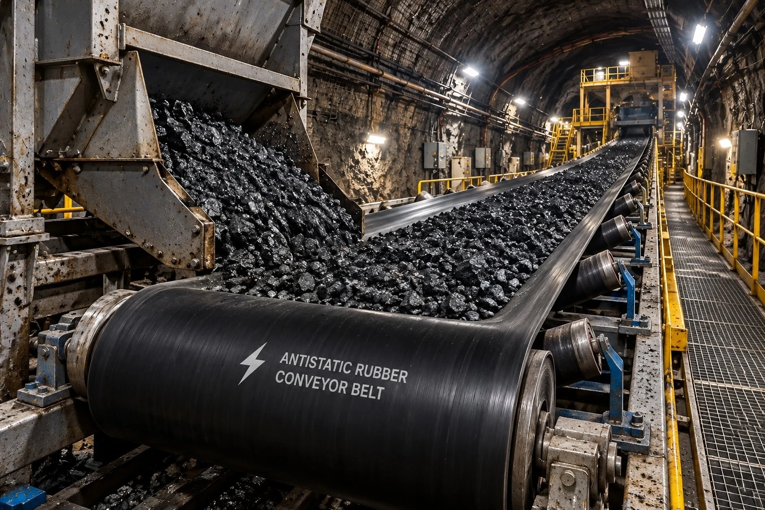
World Prime Services Antistatic Conveyor Belt is engineered for industrial conveying systems where controlled dissipation of electrostatic charge is required. The belt uses electrically conductive or static-dissipative rubber compounds and a compatible carcass construction to reduce the buildup of static electricity generated by belt movement, friction with the conveyed material and contact with conveyor components.
The product platform is intended for coal handling, power generation, ports, cement, mineral processing, chemical handling, recycling and other industrial bulk-material applications. Antistatic performance can be combined with abrasion, impact, oil, heat or flame resistance where required by the duty.
| Engineering Objective | Operational Benefit |
|---|---|
| Controlled electrical resistance | Helps dissipate electrostatic charge developed during operation |
| Conductive rubber cover system | Reduces static-charge buildup on the belt surface |
| Stable carcass construction | Supports load-carrying capability, tracking and dimensional stability |
| Application-specific compounds | Combines antistatic performance with other required properties |
| Compatibility with international testing | Can be specified and tested to recognized conductivity requirements |

Friction between the belt, pulleys, idlers and the conveyed material can generate electrostatic charge. An antistatic belt is formulated so that accumulated charge can dissipate through a controlled conductive path rather than remaining concentrated on the belt surface.
ISO 284:2025 specifies the maximum electrical resistance of a conveyor belt and the corresponding test method, with the objective of ensuring the belt is sufficiently conductive to prevent electrostatic-charge buildup during service. A commonly referenced antistatic criterion for industrial conveyor belts is electrical resistance ≤ 3 × 10⁸ Ω when tested per the applicable ISO 284 procedure. Final acceptance criteria must be defined in the purchase specification.
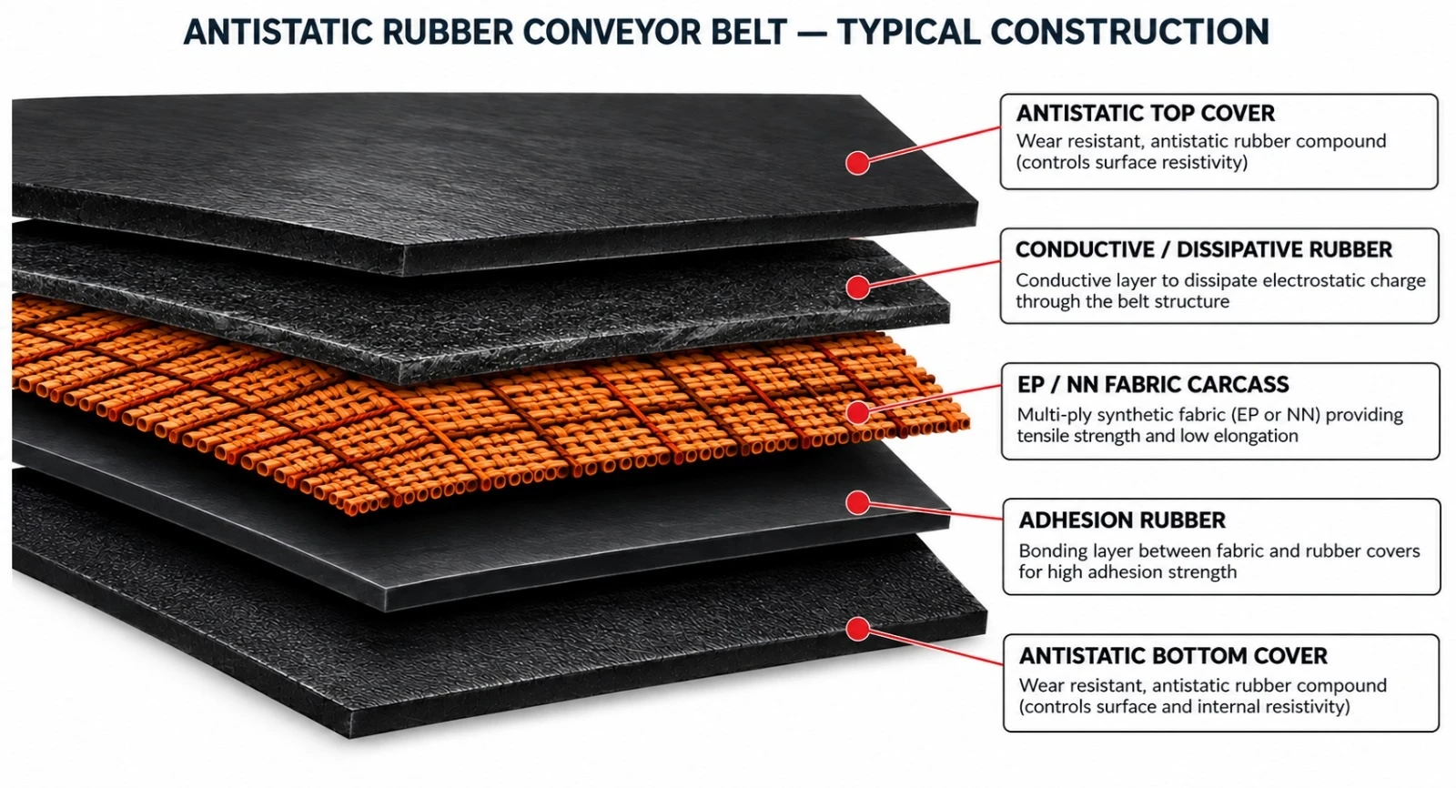
| Component | Function | Typical Options |
|---|---|---|
| Antistatic top cover | Primary conveying surface with static-dissipative behavior | Abrasion-, heat-, oil- or flame-resistant variants |
| Conductive / dissipative rubber | Supports charge dissipation through the belt body | Compound formulated for target conductivity |
| Tension carcass | Carries longitudinal operating tension | EP fabric, NN fabric or steel cord |
| Adhesion rubber | Bonds carcass and cover layers | High-adhesion bonding compound |
| Antistatic bottom cover | Pulley-side protection and static-dissipative continuity | Standard or special-service compound |
| Series | Description |
|---|---|
| AS-EP | EP Fabric Antistatic Belt — low-elongation polyester/nylon fabric construction for general and heavy-duty industrial conveying. |
| AS-NN | Nylon Fabric Antistatic Belt — flexible, impact-tolerant construction for short- to medium-distance conveyor systems. |
| AS-ST | Steel Cord Antistatic Belt — high-tensile, low-elongation construction for long-distance, high-capacity and high-tension applications. |
| AS-MP | Multi-Duty Antistatic Belt — antistatic performance combined with abrasion, oil, heat or weather resistance. |
| AS-FR | Flame-Retardant Antistatic Belt — specialized construction for service requiring both static-charge dissipation and flame resistance, subject to the applicable safety standard. |
Antistatic performance is achieved through the rubber formulation, not merely a surface treatment. Conductive ingredients are incorporated into the compound to provide controlled electrical resistance while maintaining the mechanical properties required for conveying service.
| Compound Family | Primary Duty | Typical Application | Engineering Note |
|---|---|---|---|
| AS-A | Antistatic + abrasion resistance | Coal, minerals, aggregates, cement | General heavy-duty antistatic service |
| AS-O | Antistatic + oil resistance | Oily bulk materials, recycling | Oil type and concentration to be specified |
| AS-H | Antistatic + heat resistance | Hot bulk materials | Required material and surface temperatures |
| AS-FR | Antistatic + flame resistance | Selected regulated environments | Project-specific safety standard required |
| AS-W | Antistatic + weather resistance | Outdoor terminals and exposed conveyors | For UV, ozone and weather exposure |
| Carcass | Key Characteristics | Typical Use | Selection Consideration |
|---|---|---|---|
| EP Fabric | Low elongation, dimensional stability, strong adhesion | General heavy-duty industrial conveyors | Versatile standard construction |
| NN Fabric | High flexibility and good impact absorption | Impact-oriented or shorter systems | Higher elongation than EP |
| Steel Cord | Very high tensile strength and very low elongation | Long-distance, high-capacity conveying | Engineered pulley and splice design |
| Project-Specific Hybrid | Combined characteristics | Special severe-duty conveyors | Built to technical specification |
| Parameter | Catalogue Option / Range | Remarks |
|---|---|---|
| Belt width | 300–3.200 mm | Project-dependent manufacturing range |
| Fabric strength | EP / NN classes selected by duty | Ply count based on operating tension |
| Steel cord strength | Project-specific ST classes | For long-distance or high-tension applications |
| Top cover thickness | Typically 3–20+ mm | Selected by abrasion, impact and duty |
| Bottom cover thickness | Typically 1.5–10+ mm | Selected by pulley-side wear |
| Electrical resistance | Antistatic grade per project specification | Commonly specified per ISO 284 |
| Typical antistatic criterion | ≤ 3 × 10⁸ Ω | Subject to standard edition and purchase specification |
| Edge construction | Cut edge / moulded edge | According to belt type |
| Splice method | Hot vulcanized preferred for critical service | Depends on carcass construction |
| Temperature range | Compound-dependent | Must be stated at enquiry stage |
Electrical resistance must be verified on representative belt samples, using the procedure required by the applicable standard or the customer specification. ISO 284:2025 is the current international standard covering the electrical conductivity of conveyor belts and its test method.
| Test / Requirement | Purpose | Catalogue Recommendation |
|---|---|---|
| Electrical resistance test | Verify antistatic performance | Specify ISO 284 or approved equivalent |
| Sample conditioning | Control test repeatability | Follow the current standard |
| Production traceability | Link results to manufacturing batch | Maintain batch identification |
| Retest after compound changes | Confirm conductivity remains within specification | Recommended for engineered variants |
| On-site verification | Assess installed system behavior | Inspect grounding and conveyor equipment |
Important: an antistatic belt is only one element of electrostatic risk control. Conveyor structures, pulleys, idlers, bearings, grounding/bonding, material properties, dust concentration, humidity and local safety regulations must also be considered.
| Industry | Typical Materials | Why Antistatic Performance Matters |
|---|---|---|
| Coal & Power Handling | Coal and dry fuel materials | Dry dust and friction can contribute to charge buildup |
| Ports & Terminals | Coal, ore, minerals, dry bulk cargo | High speeds and continuous operation require controlled static behavior |
| Cement | Limestone, clinker, dry powders | Handling dry particulates can generate static charge |
| Chemical Industry | Selected dry bulk materials | Static control may be required depending on material and process |
| Grain & Biomass | Dry grain, biomass, agricultural materials | Dust-sensitive environments require electrostatic risk assessment |
| Mining & Minerals | Ore, coal and processed minerals | Heavy-duty conveying combined with static-control requirements |
| Recycling | Varied dry industrial materials | Variable materials and friction can generate charge buildup |
Correct installation is essential to preserving mechanical performance and electrical continuity. The conveyor system should be inspected for grounding/bonding, pulley and idler condition, belt tracking and splice integrity before commissioning.
| Inspection Item | Recommended Check | Reason |
|---|---|---|
| Belt cover condition | Inspect wear, cracking, contamination and deep damage | Severe degradation may affect operation |
| Splices | Check for separation, lifting or mechanical damage | Maintains structural and electrical continuity |
| Pulleys and idlers | Check rotation, buildup and alignment | Reduces abnormal friction and heating |
| Grounding / bonding | Inspect per site electrical procedure | Supports controlled dissipation |
| Material buildup | Remove excessive insulating deposits | Deposits can affect operation and conductivity |
| Electrical resistance | Periodic testing where required | Confirms ongoing compliance |
| Control Item | Purpose | Typical Stage |
|---|---|---|
| Belt width and thickness | Confirm dimensional compliance | Final inspection |
| Cover thickness | Verify ordered construction | Production / final |
| Carcass identification | Confirm fabric or steel cord construction | Production |
| Adhesion properties | Verify ply integrity | Laboratory control |
| Cover physical properties | Confirm compound performance | Laboratory control |
| Electrical resistance | Verify antistatic performance | Laboratory / final acceptance |
| Visual inspection | Detect visible defects | Final inspection |
| Roll marking and traceability | Product identification and batch control | Dispatch |
Specifications may be developed with reference to ISO 284:2025 for electrical conductivity, together with applicable construction standards such as ISO 14890 for textile conveyor belts and ISO 15236 for steel cord conveyor belts. Where flame resistance, underground mining or potentially explosive atmospheres are involved, the project specification must also define the applicable local and international safety requirements.
| Project / Site | |
| Conveyed Material | |
| Bulk Density | |
| Maximum Lump Size | |
| Capacity (t/h) | |
| Belt Width (mm) | |
| Belt Speed (m/s) | |
| Center Distance (m) | |
| Inclination (°) | |
| Carcass / Required Strength | |
| Top / Bottom Cover (mm) | |
| Required Electrical Resistance | |
| Required Standard | |
| Special Compound Requirement | |
| Hazardous Area / Fire Requirement | |
| Splice Requirement | |
| Ambient / Material Temperature | |
| Additional Operating Notes |
High-Tensile Flame-Resistant Belting for Long-Distance, Heavy-Load & Safety-Critical Bulk Handling

World Prime Services Fire-Resistant Steel Cord Conveyor Belt is engineered for high-tension, long-distance and heavy-load bulk-material conveying where fire performance and operational safety are critical design requirements.
The belt combines longitudinal high-tensile steel cords with fire-resistant rubber cover compounds and a high-adhesion skim system. Depending on the application, the construction may also incorporate antistatic properties, transverse breakers, rip-protection layers and special safety-qualified rubber systems for underground or other regulated installations.
| Engineering Objective | Operational Benefit |
|---|---|
| High tensile strength | Supports long-distance and heavy-load conveying with low elongation |
| Fire-resistant cover system | Helps reduce flame propagation under defined test conditions |
| Low elongation steel cord carcass | Improves tracking, take-up stability and dynamic control |
| High steel-cord adhesion | Supports load transfer and structural integrity |
| Optional antistatic performance | Supports dissipation of electrostatic charge where specified |
| Optional anti-rip reinforcement | Improves resistance to longitudinal tear propagation |
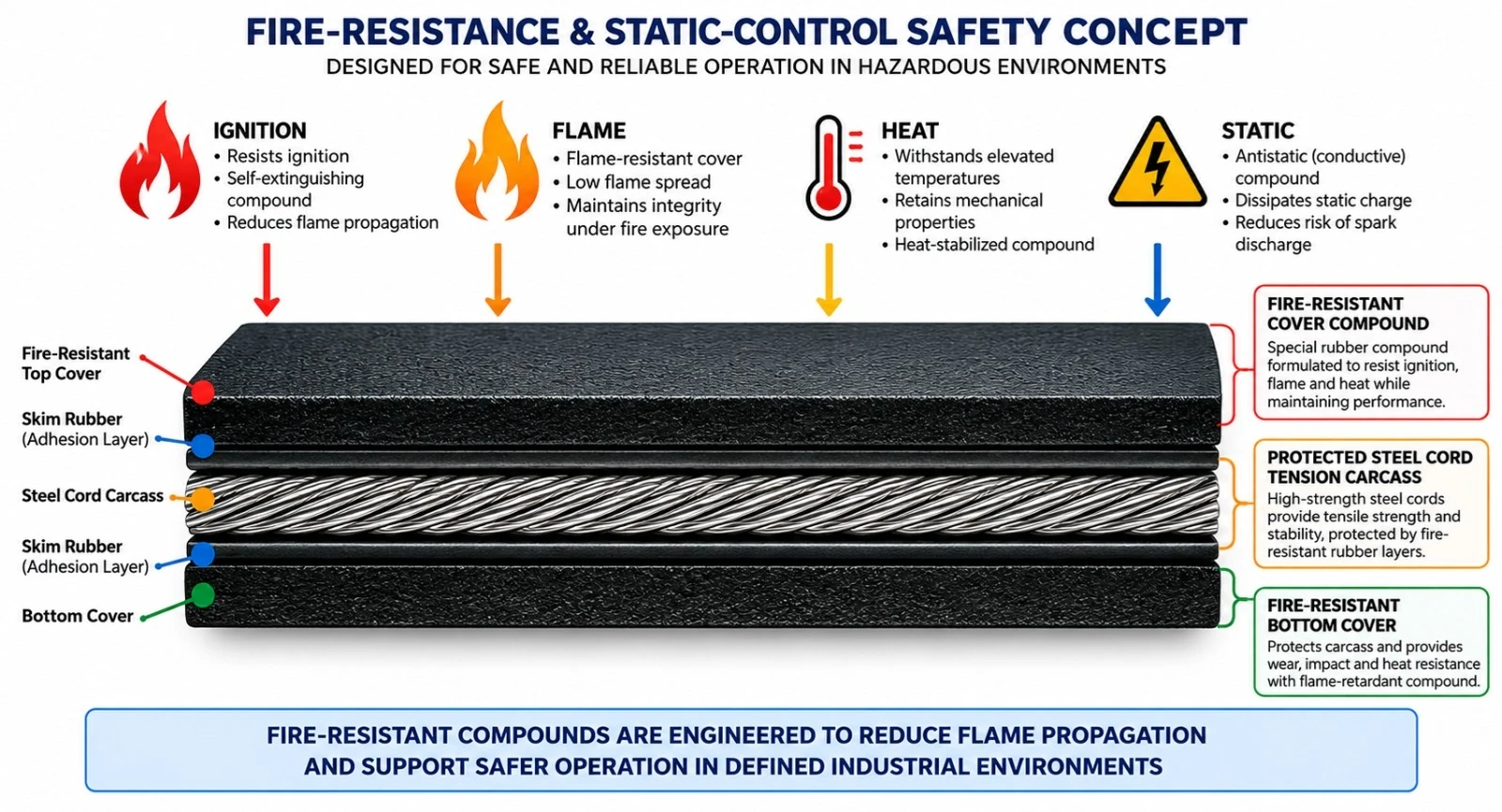
Fire-resistant steel cord belting is designed to combine the mechanical advantages of a steel cord tension member with cover and skim compounds formulated for reduced flammability. Fire behavior must be evaluated using the governing standard and the exact service category.
Fire resistance does not mean that the belt is non-combustible. It means the belt is engineered to meet defined flame-test, flame-propagation or related safety requirements. Where dust, coal, combustible material or underground operation is involved, antistatic and other safety properties may also be mandatory.
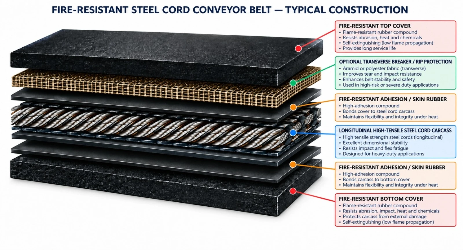
| Component | Engineering Function | Typical Options |
|---|---|---|
| Fire-resistant top cover | Primary conveying surface and fire-protection layer | FR / FRAS / underground-qualified compound |
| Fire-resistant adhesion / skim rubber | Bonds steel cords to covers and transfers dynamic load | High-adhesion flame-resistant system |
| Longitudinal steel cord carcass | Carries operating tension | ST-class steel cords |
| Transverse breaker / rip protection | Improves impact and tear resistance | Textile breaker / transverse steel or synthetic cords |
| Fire-resistant bottom cover | Protects pulley-side carcass | FR or FRAS compound |
| Edge construction | Protects reinforcement from environmental ingress | Moulded or engineered edge |
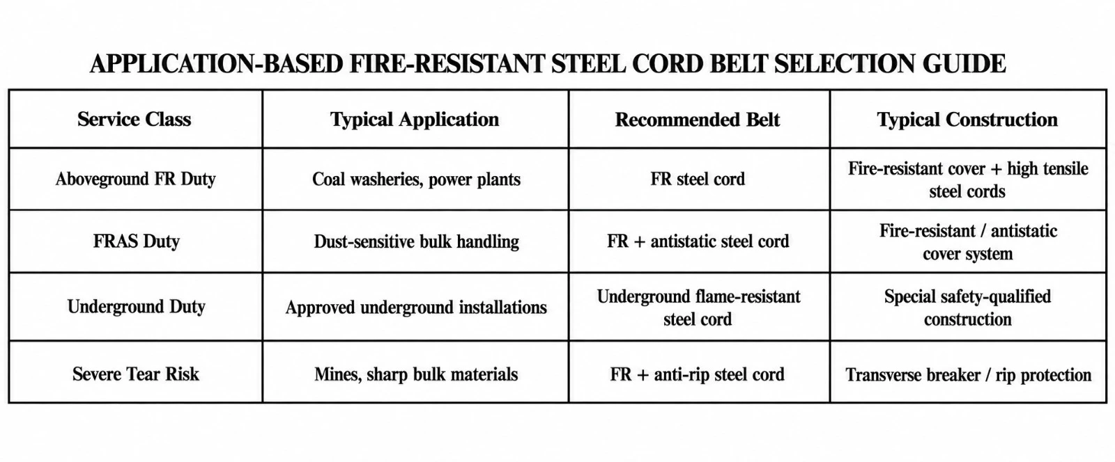
FR-ST-G Series — Flame-Resistant Steel Cord Belt for General Use. Designed for aboveground coal washeries, power plants, bulk terminals and selected non-coal underground or industrial applications where fire-resistant performance is required by the project specification.
FR-ST-U Series — Flame-Resistant Steel Cord Belt for Underground Use. Special safety-oriented construction for underground installations where applicable regulations require flame-resistant and related safety properties.
FRAS-ST Series — Fire-Resistant & Antistatic Steel Cord Belt. Combines flame-resistant rubber with controlled electrical resistance for static-charge dissipation.
FR-AR-ST Series — Fire-Resistant Anti-Rip Steel Cord Belt. Adds transverse breaker or anti-rip reinforcement for sharp, heavy or penetrating materials.
FR-X Series — Engineered Safety-Critical Steel Cord Belt. Project-specific configuration combining fire resistance with high tension, special cover thickness, rip protection, monitoring systems or other site requirements.
Steel cord reinforcement provides very high tensile strength with low operational elongation, making it suitable for long center distances, high capacities and high belt tensions. Cord diameter, pitch, construction and adhesion system are selected from the required nominal belt strength and splice design.
| Design Element | Function | Engineering Consideration |
|---|---|---|
| Steel cord diameter | Defines individual cord strength | Matched to nominal belt strength |
| Cord pitch | Controls cord density across belt width | Affects strength distribution and splice layout |
| Galvanized cord surface | Supports rubber-to-steel adhesion and corrosion protection | Requires compatible skim compound |
| Skim rubber | Encapsulates cords and transfers load | Critical for adhesion and fatigue resistance |
| Low elongation | Maintains dimensional stability | Reduces take-up movement compared with textile carcass |
| Cover System | Primary Property | Typical Application |
|---|---|---|
| FR | Flame-resistant | General industrial fire-risk environments |
| FRAS | Flame-resistant + antistatic | Coal handling and dust-sensitive bulk systems |
| Underground FR | Special flame and safety performance | Approved underground installations |
| FR + Abrasion | Fire resistance + high wear resistance | Coal, minerals and abrasive bulk materials |
| FR + Anti-Rip | Fire resistance + tear propagation control | Sharp or penetrating materials |
Compound selection must consider flame performance together with abrasion, temperature, oil contamination, weather exposure and electrical-resistance requirements.
| Configuration | Typical Environment | Key Engineering Focus |
|---|---|---|
| General-use flame-resistant steel cord belt | Aboveground coal washeries, power plants, bulk handling | Fire-resistant cover performance and high tensile strength |
| FRAS general-use steel cord belt | Coal and dust-sensitive industrial systems | Fire resistance plus electrical conductivity |
| Underground flame-resistant steel cord belt | Regulated underground installations | Special safety requirements, flame behavior and statutory compliance |
| Anti-rip flame-resistant belt | Mines and heavy bulk handling with piercing risk | Fire performance plus transverse rip protection |
Underground use should never be inferred from a general FR designation alone. The exact underground approval, standard and local regulatory requirement must be stated in the purchase specification.
| Parameter | Catalogue Option / Range | Remarks |
|---|---|---|
| Belt width | Approx. 600–3,200+ mm | Project-dependent |
| Nominal belt strength | Approx. ST 500 to ST 7500 — engineering range | Final class by conveyor calculation |
| Top cover thickness | Typically 6–15+ mm | Selected by wear, impact and fire requirements |
| Bottom cover thickness | Typically 4–10+ mm | Selected by pulley-side duty |
| Cover system | FR / FRAS / underground FR / engineered | Project-specific safety class |
| Electrical resistance | Antistatic option available | Project acceptance criterion required |
| Rip protection | Optional breaker / transverse reinforcement | Recommended for severe-duty service |
| Splice method | Hot vulcanized | Designed to steel cord class and standard |
| Monitoring | Optional rip-detection / cord-monitoring compatibility | Project-specific |
| Indicative Class | Typical Duty | General Engineering Characteristic |
|---|---|---|
| ST 500–1000 | Moderate steel-cord duty | Lower tension, shorter long-distance systems |
| ST 1250–2000 | Heavy industrial duty | Coal, power and mining applications |
| ST 2500–3500 | High-tension long-distance duty | High capacity and extended center distance |
| ST 4000–5000 | Very high-tension duty | Critical long overland systems |
| ST 5400–7500 | Extreme engineered duty | Project-specific high-strength applications |
Actual preferred classes and dimensional requirements should be selected according to the applicable ISO 15236 series or customer-approved design specification.
| Property / Test | Purpose | Typical Reference |
|---|---|---|
| Flame resistance | Assess flame persistence / propagation behavior | ISO 340 or applicable local requirement |
| Electrical conductivity | Assess static-charge dissipation | ISO 284 |
| Steel cord belt safety | Underground-specific requirements where applicable | ISO 15236-3 |
| Mechanical construction | Dimensions and mechanical requirements | ISO 15236-1 |
| Splices | Splice design and performance | ISO 15236-4 |
A current industrial tender example for an ST 1600 FRAS steel cord belt specified 10 mm top cover, 5 mm bottom cover, electrical surface resistance not exceeding 300 megaohms and compliance references to DIN 22131 / ISO 15236. Such values are application-specific examples and should not be treated as universal catalogue guarantees.
| Reinforcement | Function | Best Fit |
|---|---|---|
| Textile breaker | Improves impact distribution and local damage control | General heavy-duty FR service |
| Transverse synthetic cord | Improves longitudinal rip resistance | Sharp bulk materials |
| Transverse steel cord | High-strength rip protection | Severe piercing risk |
| Periodic rip-stop zones | Localized damage arrest strategy | Critical long-distance systems |
| Electronic rip detection compatibility | Supports early damage detection | High-value conveyor systems |
| Industry | Typical Materials | Primary Requirement |
|---|---|---|
| Coal Handling | Coal and fuel materials | FR / FRAS performance and heavy-duty strength |
| Power Plants | Coal, biomass and fuel handling | Long-distance reliability and fire safety |
| Mining | Ore, coal and bulk minerals | High tension, abrasion and rip resistance |
| Coal Washeries | Processed coal | Fire-resistant general-use steel cord belt |
| Ports & Terminals | Coal and bulk commodities | High capacity and continuous duty |
| Non-Coal Underground Mining | Minerals and ore | Safety-class belt as required by regulation |
| Metallurgy | Raw materials and bulk solids | Heavy-duty steel cord construction |
| Design Factor | Engineering Impact |
|---|---|
| Drive pulley diameter | Controls steel cord bending fatigue |
| Tail / bend pulley diameter | Influences reverse bending and carcass life |
| Take-up travel | Accommodates elastic stretch and operational movement |
| Drive traction | Depends on belt tension and pulley lagging |
| Belt Speed (m/s) | Influences dynamic load and heat generation |
| Transition distance | Controls edge and cord stress |
| Fire-risk zoning | Influences cover and safety-system selection |
Steel cord flame-resistant conveyor belts require engineered hot-vulcanized splices. Splice length, step arrangement, cord layout and splice materials depend on the belt strength class and the applicable standard.
| Inspection Point | What to Check | Recommended Action |
|---|---|---|
| Top cover | Cuts, burning, glazing, cracking or severe wear | Repair and investigate source |
| Edges | Cord exposure or delamination | Immediate repair |
| Splices | Cracking, separation or cord movement | Engineered inspection |
| Pulley lagging | Slip or heat generation | Restore traction |
| Rip-protection system | Damage or detector malfunction | Repair / test system |
| Grounding / conductivity path | Loose bonding or contamination | Restore electrical continuity |
| Carcass monitoring | Cord damage where monitoring is installed | Trend and act on alarms |
| Control Item | Purpose | Typical Stage |
|---|---|---|
| Belt width / thickness | Dimensional compliance | Final inspection |
| Steel cord layout | Verify cord pitch and construction | Production |
| Cover physical properties | Confirm compound consistency | Laboratory |
| Cord adhesion / pull-out | Verify steel-rubber bonding | Laboratory |
| Flame-resistance testing | Verify specified fire performance | Qualification / acceptance |
| Electrical resistance testing | Verify antistatic performance where specified | Qualification / acceptance |
| Splice qualification | Confirm joint performance | Project-specific |
| Traceability | Identify production batch and roll | Dispatch |
| Reference | Relevance |
|---|---|
| ISO 15236-1 | Steel cord conveyor belts — design, dimensions and mechanical requirements for general use |
| ISO 15236-2 | Preferred steel cord belt types |
| ISO 15236-3 | Special safety requirements for steel cord conveyor belts used underground |
| ISO 15236-4 | Vulcanized steel cord belt joints |
| ISO 340 | Flame resistance — requirements and test method |
| ISO 284 | Electrical conductivity / antistatic test method |
| DIN 22103 | Historic German flame-resistant steel cord belt standard; current project use should verify status and replacement references |
Project specifications should identify the exact standard edition and any local mining, underground or fire-safety approval. General-use FR belts and underground-approved belts are not automatically interchangeable.
| Project / Site | |
| Industry | |
| Aboveground / Underground | |
| Conveyed Material | |
| Capacity (t/h) | |
| Bulk Density | |
| Maximum Lump Size | |
| Belt Width (mm) | |
| Belt Speed (m/s) | |
| Center Distance (m) | |
| Inclination (°) | |
| Required ST Strength Class | |
| Top / Bottom Cover (mm) | |
| Required Fire Standard | |
| Required Antistatic Standard | |
| Electrical Resistance Criterion | |
| Underground Approval Required? | |
| Anti-Rip Reinforcement Required? | |
| Rip Detection / Monitoring Required? | |
| Drive Pulley Diameter | |
| Tail Pulley Diameter | |
| Take-Up Travel | |
| Splice Standard / Requirement | |
| Ambient Temperature | |
| Material Temperature | |
| Applicable Regulation / Standard | |
| Additional Operating Notes |
EPDM & EPM High-Temperature Rubber Belting for Clinker, Sinter, Coke, Foundry and Metallurgical Service

World Prime Services High-Temperature Resistant Conveyor Belt is engineered for conveying hot bulk materials under thermal conditions that exceed the practical capability of conventional general-purpose rubber belting.
The product family uses high-temperature-resistant EPDM or EPM-based cover systems, thermally stable adhesion compounds and selected load-bearing carcasses. The belt is intended for demanding applications including cement clinker, sintered ore, coke, foundry materials, hot ash, metallurgical products and other elevated-temperature bulk solids.
The final belt specification must be based on actual material temperature, belt-surface temperature, contact duration, particle size, loading frequency, belt speed, cooling interval, ambient temperature and mechanical duty.
| Design Objective | Engineering Benefit |
|---|---|
| High-temperature cover compound | Improved resistance to thermal hardening, cracking and ageing |
| Thermally stable adhesion system | Helps preserve cover-to-carcass integrity |
| Heat-stabilized carcass | Supports dimensional stability under repeated thermal cycles |
| Optimized cover thickness | Provides additional thermal protection to the carcass |
| Optional breaker reinforcement | Improves resistance to hot-lump impact and penetration |
| Project-specific temperature grade | Matches compound system to real thermal exposure |
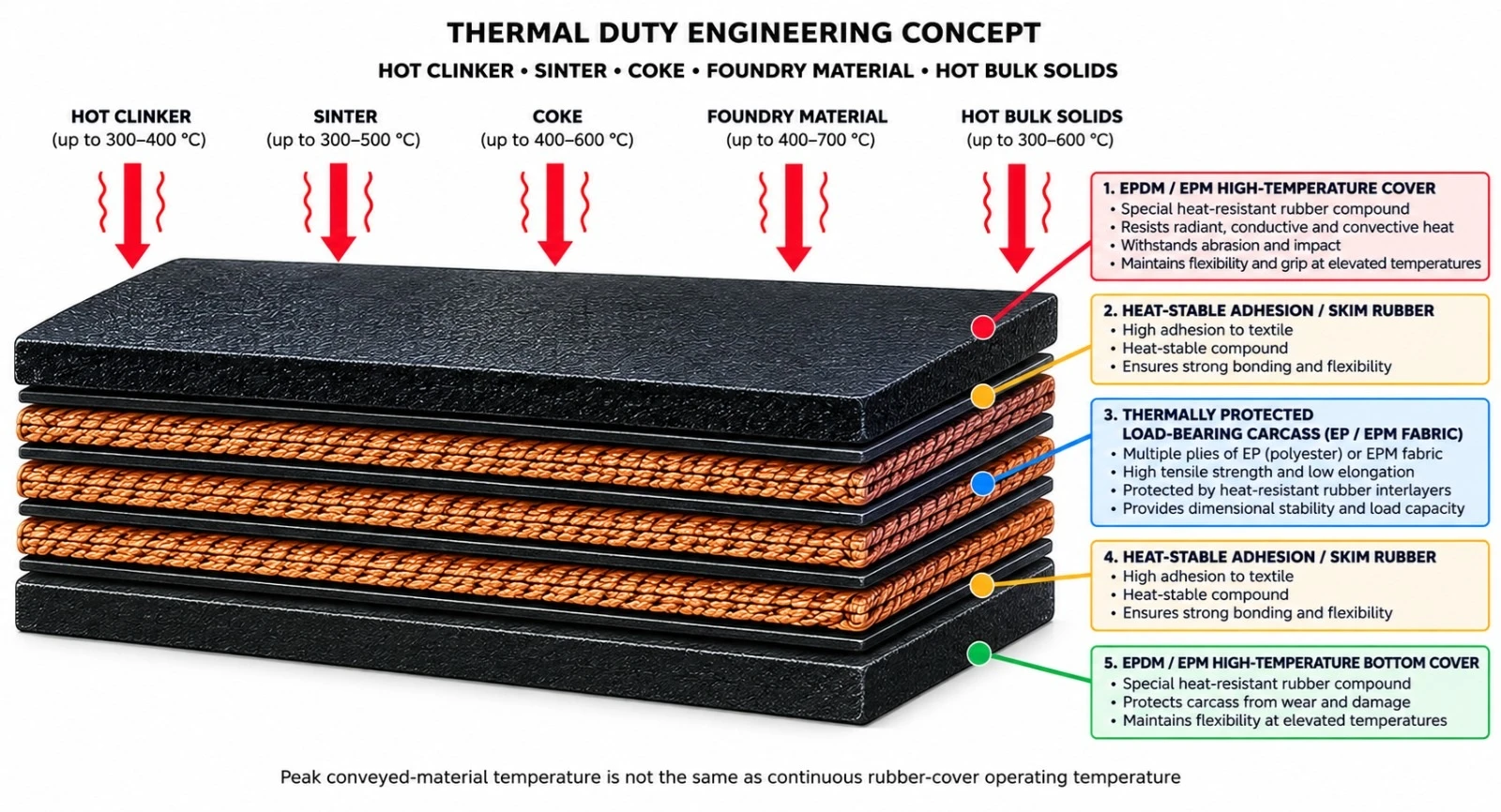
High-temperature belt selection must distinguish between continuous conveyed-material temperature, short-duration peak material temperature and the actual temperature reached by the rubber cover. These values are not interchangeable.
A belt may encounter very hot particles or lumps for a limited period while the moving belt, material bed depth, ambient airflow and return run allow partial cooling. Therefore, a stated peak material temperature of up to 400°C must not be interpreted as a claim that EPDM or EPM rubber can operate continuously at 400°C.
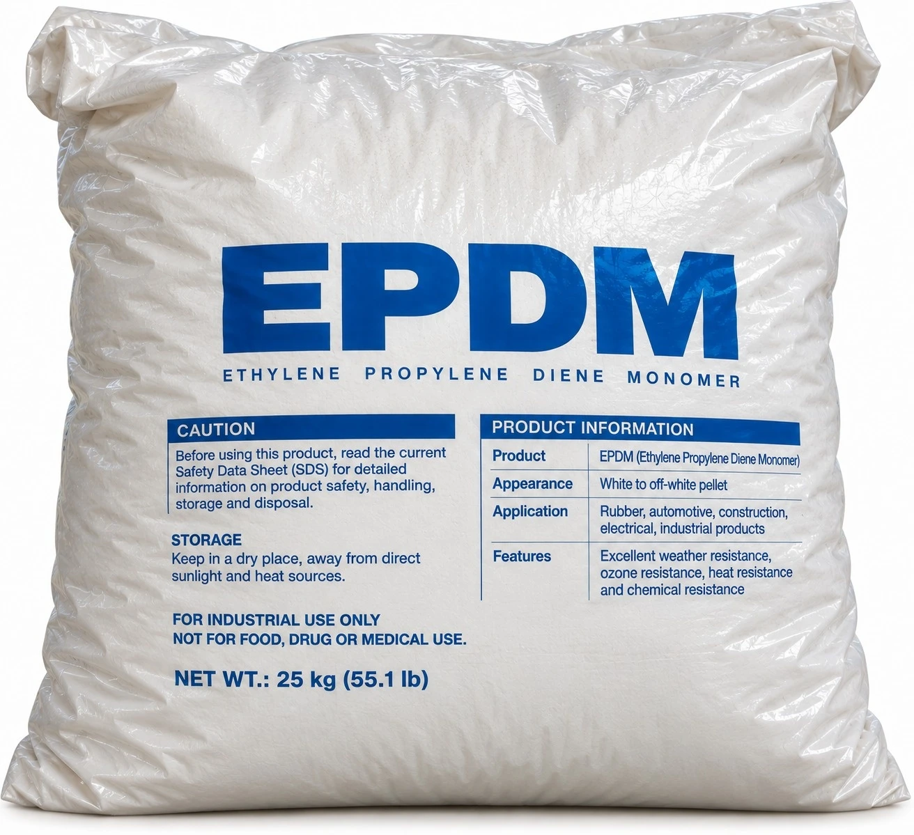
EPDM — ethylene propylene diene monomer — is widely used in heat-resistant conveyor-belt compounds because of its strong resistance to heat ageing, ozone, weathering and many polar media. In conveyor-belt service, the practical temperature capability depends on the complete compound formulation, curing system, cover thickness and duty cycle.
| EPDM Thermal Duty | Indicative Engineering Range | Catalogue Interpretation |
|---|---|---|
| Continuous high-temperature duty | Typically engineered around approximately 150–180°C material-service classes | Final limit depends on compound and belt design |
| Enhanced / ultra-high thermal duty | Specialized systems may be specified around approximately 180–200°C continuous material duty | Requires premium compound and validated application data |
| Short-duration hot exposure | Approximately 200°C or above may be tolerated by selected constructions for limited exposure | Not equivalent to continuous operation |
| Extreme conveyed-material peak | Up to approximately 400°C may be considered only as brief peak material exposure in specially engineered systems | Requires thermal-duty analysis; not continuous rubber temperature |
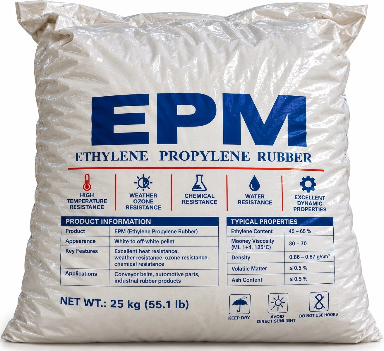
EPM — ethylene propylene rubber without the diene termonomer used in EPDM — belongs to the ethylene-propylene elastomer family and is valued for heat, ozone and weather resistance. Because EPM has a saturated polymer backbone, its curing chemistry and compound design differ from EPDM.
For high-temperature conveyor belting, EPM-based formulations should be treated as engineered compounds rather than assigned a universal temperature limit. Depending on formulation and validation, EPM systems can be positioned for severe continuous thermal duty, with short-duration material peaks substantially above the normal continuous service range.
| EPM Thermal Duty | Indicative Engineering Range | Catalogue Interpretation |
|---|---|---|
| Continuous high-temperature duty | Typically engineered in approximately 150–180°C material-service territory | Compound-specific validation required |
| Severe continuous duty | Specialized formulations may target approximately 180–200°C material duty | Application engineering required |
| Short-duration exposure | Selected systems may tolerate brief higher-temperature contact | Duration and cooling cycle are critical |
| Extreme conveyed-material peak | Peak material temperatures approaching 400°C may be considered only for specially engineered intermittent exposure | Not a continuous EPM rubber-cover temperature rating |
| Property | EPDM | EPM |
|---|---|---|
| Polymer family | Ethylene-propylene-diene elastomer | Ethylene-propylene copolymer elastomer |
| Heat ageing resistance | Excellent when correctly compounded | Excellent when correctly compounded |
| Ozone / weather resistance | Excellent | Excellent |
| Cure flexibility | Diene sites permit conventional sulfur or peroxide systems depending on formulation | Typically requires cure systems suited to saturated backbone |
| High-temperature belt use | Widely established in heat-resistant conveyor-belt cover compounds | Used in specialized heat-resistant compound systems |
| Typical catalogue positioning | High to ultra-high thermal duty | High to severe thermal duty, formulation-dependent |
| 400°C statement | Only brief peak conveyed-material exposure in engineered systems | Only brief peak conveyed-material exposure in engineered systems |
The following World Prime Services grade architecture is an engineering selection framework rather than a universal polymer limit. Final acceptance temperatures must be confirmed against approved compound data and operating conditions.
| Grade | Cover System | Indicative Continuous Material Duty | Indicative Peak Material Exposure | Typical Application |
|---|---|---|---|---|
| HT-150 | EPDM / EPM engineered compound | Up to approximately 150°C | Short peaks above continuous duty | Hot bulk solids, moderate clinker duty |
| HT-180 | Premium EPDM / EPM | Up to approximately 180°C | Approximately 200°C short-duration territory | Clinker, coke, hot minerals |
| HT-200 | Ultra-high-temperature engineered compound | Up to approximately 200°C in validated applications | Higher intermittent peaks | Severe cement and metallurgical duty |
| HT-400 PEAK | Special project-engineered EPDM / EPM-based belt system | Continuous duty must remain within validated belt limit | Peak conveyed-material exposure up to 400°C, brief/intermittent only | Extreme hot-lump or transient process conditions |
The 400°C figure in this catalogue refers exclusively to possible peak temperature of the conveyed material in a specially engineered, intermittent exposure scenario. It is not a 400°C continuous operating temperature for the rubber cover.
Suitability for such peaks depends on contact time, particle size, material bed depth, belt speed, loading pattern, top-cover thickness, thermal conductivity, cooling interval and carcass temperature. Direct continuous contact with material at 400°C can rapidly damage organic elastomers and must not be specified without project-specific thermal validation.
| Thermal Variable | Why It Matters |
|---|---|
| Peak material temperature | Defines the maximum transient thermal input |
| Continuous material temperature | Controls long-term thermal ageing |
| Belt-surface temperature | More directly reflects rubber thermal stress |
| Contact duration | Longer contact increases heat penetration |
| Particle / lump size | Large hot lumps create concentrated thermal loading |
| Belt Speed (m/s) | Influences contact time and cooling cycle |
| Cover thickness | Provides thermal mass and carcass protection |
| Return-run cooling | Controls temperature recovery before reloading |

| Component | Engineering Function | Typical Option |
|---|---|---|
| High-temperature top cover | Primary heat and wear barrier | EPDM / EPM high-temperature compound |
| Thermally stable skim rubber | Maintains cover-to-carcass bonding | High-temperature adhesion system |
| Load-bearing carcass | Carries operating tension | EP / high-modulus textile / project-specific steel cord |
| Optional breaker | Distributes impact and limits local damage | Textile or transverse reinforcement |
| Bottom cover | Protects pulley-side carcass | Heat-resistant compound |
| Edge construction | Protects reinforcement | Cut edge / moulded edge |
EP fabric is a preferred textile carcass option for high-temperature conveyor belts because of its low elongation and dimensional stability. High-strength EP constructions may be used for heavier duty. Steel cord construction can be engineered for long-distance, high-tension systems where the thermal package is compatible with the carcass and splice design.
The top cover must provide both thermal resistance and mechanical durability. High-temperature cover performance is only effective if the skim and adhesion system also retains bond strength under thermal cycling. Cover thickness should therefore be selected as part of the complete thermal barrier.
HT-EPDM Series — High-temperature belt using EPDM-based cover compounds.
HT-EPM Series — Specialized high-temperature belt using EPM-based cover technology.
HT-EPDM AR Series — EPDM heat-resistant belt with optional anti-rip or breaker reinforcement.
HT-EPM Severe Duty Series — EPM-based system for demanding thermal cycling.
HT-ST Series — High-temperature steel cord belt for high-tension project-specific service.
HT-400 PEAK Series — Specially engineered belt package for brief conveyed-material temperature peaks approaching 400°C, subject to thermal validation.
| Parameter | Catalogue Option / Range | Remarks |
|---|---|---|
| Belt width | Approx. 400–3,200+ mm | Project-dependent |
| Carcass | EP / high-strength textile / steel cord | Selected by tension and distance |
| Top cover | Typically 4–20+ mm | Thermal and impact duty dependent |
| Bottom cover | Typically 2–8+ mm | Project-dependent |
| Cover polymer | EPDM / EPM engineered compound | Grade-dependent |
| Continuous thermal grade | HT-150 / HT-180 / HT-200 engineered classes | Subject to compound validation |
| Extreme peak grade | HT-400 PEAK | Brief conveyed-material peak only |
| Breaker reinforcement | Optional | For impact / penetration risk |
| Splice | Hot vulcanized preferred | Thermally compatible materials required |
| Industry | Typical Hot Material | Primary Requirement |
|---|---|---|
| Cement | Clinker | Heat, abrasion and impact resistance |
| Iron & Steel | Sintered ore / hot process materials | Severe thermal duty |
| Coke Plants | Hot coke | Heat ageing and abrasion resistance |
| Foundries | Foundry sand / hot cast process materials | Thermal cycling resistance |
| Metallurgy | Hot minerals and bulk solids | Continuous high-temperature reliability |
| Power / Waste | Hot ash and residues | Heat and ageing resistance |
Material temperature should not be used as the sole belt-selection criterion. The rubber cover may run cooler than the conveyed material when contact is brief and cooling is effective, or it may accumulate damaging heat when exposure is continuous. Surface-temperature measurement during trial operation is strongly recommended for severe applications.
Thermal ageing can increase hardness, reduce elongation, reduce tensile properties and weaken adhesion. Belt life is influenced by thermal cycling as well as mechanical wear. Monitoring changes in cover hardness, cracking and splice condition provides useful evidence of ageing severity.
Large hot lumps combine thermal shock with mechanical impact. Loading-zone design should minimize drop height, control impact energy and distribute material across the belt. Breaker reinforcement may be specified where hot sharp lumps create penetration or rip risk.
Minimum pulley diameter, transition distance and take-up design must match carcass construction and belt thickness. Heat ageing can reduce flexibility, making correct pulley sizing particularly important for long-term belt integrity.
Hot-vulcanized splicing is generally preferred for critical high-temperature service. Splice rubber, skim compounds and cover compounds must be thermally compatible with the parent belt. The splice design and cure parameters must follow the approved belt construction.
Verify conveyor alignment, pulley condition, loading-zone geometry and take-up settings before commissioning. During initial hot operation, monitor belt tracking, splice condition, belt-surface temperature and localized thermal hot spots.
| Inspection Point | Typical Symptom | Recommended Action |
|---|---|---|
| Top cover | Hardening / cracking | Review temperature and grade suitability |
| Cover surface | Blistering / softening | Check peak exposure and cooling |
| Adhesion | Delamination | Repair or replace affected section |
| Splice | Cracking / separation | Immediate engineered inspection |
| Loading zone | Localized burns | Improve loading distribution / cooling |
| Carcass | Exposure or thermal damage | Remove from service if integrity is compromised |
| Control Item | Purpose |
|---|---|
| Cover tensile strength | Verify mechanical performance |
| Elongation at break | Evaluate flexibility retention |
| Hardness after heat ageing | Evaluate thermal ageing behavior |
| Cover-to-ply adhesion | Verify structural integrity |
| Ply-to-ply adhesion | Verify carcass bonding |
| Dimensional inspection | Confirm width and cover thickness |
| Batch traceability | Identify production and compound system |
ISO 4195:2012 remains the published ISO reference for conveyor belts with heat-resistant rubber covers, specifying requirements and test methods based on changes in properties after heat exposure. A technically revised third edition was in the final-draft / under-development process in 2026, including a proposed Class 4 test level at 175°C.
| Thermal Severity | Indicative Material Duty | Recommended System | Engineering Note |
|---|---|---|---|
| High | Up to ~150°C continuous material duty | HT-150 EPDM / EPM | Confirm belt-surface temperature |
| Very High | Up to ~180°C continuous material duty | HT-180 Premium EPDM / EPM | Enhanced thermal compound |
| Ultra High | Up to ~200°C in validated applications | HT-200 engineered system | Application-specific validation |
| Extreme Transient | Brief peaks approaching 400°C | HT-400 PEAK engineered system | Not continuous rubber temperature; thermal study mandatory |
| Project / Site | |
| Industry | |
| Conveyed Material | |
| Normal Material Temperature (°C) | |
| Maximum Continuous Material Temperature (°C) | |
| Maximum Peak Material Temperature (°C) | |
| Peak Duration (seconds / minutes) | |
| Estimated Belt Surface Temperature (°C) | |
| Material Lump Size | |
| Capacity (t/h) | |
| Bulk Density | |
| Belt Width (mm) | |
| Belt Speed (m/s) | |
| Center Distance (m) | |
| Inclination (°) | |
| Preferred Cover Polymer (EPDM / EPM) | |
| Required Carcass Type | |
| Required Belt Strength | |
| Top Cover (mm) | |
| Bottom Cover (mm) | |
| Breaker / Anti-Rip Requirement | |
| Drive Pulley Diameter | |
| Tail Pulley Diameter | |
| Take-Up Type | |
| Splice Requirement | |
| Ambient Temperature | |
| Cooling Interval / Method | |
| Applicable Standard / Customer Specification | |
| Additional Operating Notes |
EPDM and EPM temperature capability is compound-specific. The catalogue ranges are engineering selection bands based on published conveyor-belt industry practice and must not be interpreted as universal polymer ratings. Any reference to 400°C means a brief peak temperature of conveyed material under specially engineered intermittent conditions; it does not mean continuous EPDM or EPM rubber operation at 400°C.
Final belt approval must be based on validated compound data, applicable heat-ageing tests, conveyor operating conditions and the customer's approved technical specification.
Safety-Oriented Rubber Conveyor Belting for Fire-Risk, Coal, Mining & Industrial Bulk Handling

World Prime Services Flame-Retardant Conveyor Belt is engineered for bulk-material handling systems where reduced flammability, controlled flame behavior and operational fire safety are critical design requirements.
The product range includes textile-reinforced constructions for general industrial service and project-specific configurations for mining, coal, power generation, ports and other environments where flame-retardant or flame-retardant-antistatic performance is specified. Depending on the duty, the belt may also incorporate abrasion resistance, impact resistance, antistatic performance and transverse anti-rip reinforcement.
| Engineering Objective | Operational Benefit |
|---|---|
| Reduced flame propagation | Supports safer operation under defined fire-test requirements |
| High carcass strength | Provides reliable load carrying in heavy-duty service |
| Strong cover-to-carcass adhesion | Maintains belt integrity under repeated flexing |
| Optional antistatic performance | Helps dissipate static charge where specified |
| Optional anti-rip reinforcement | Improves resistance to tear propagation |
| Application-specific compound design | Allows fire performance to be combined with abrasion and environmental requirements |

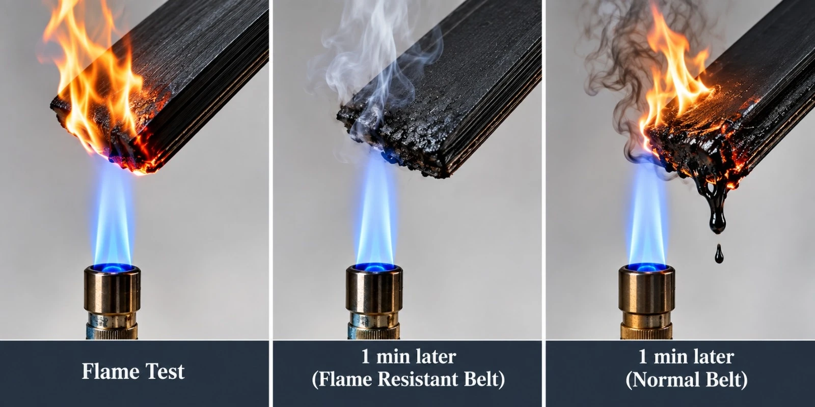
Flame-retardant conveyor belting uses specially formulated rubber compounds designed to reduce flame persistence and propagation after exposure to a defined ignition source. Performance must be verified using the applicable standard and test method.
Flame retardance does not mean that the belt is non-combustible. It means the belt is engineered to satisfy defined laboratory-scale flammability requirements. In coal, dust-sensitive or other hazardous environments, electrical conductivity and static-charge control may also form part of the safety specification.
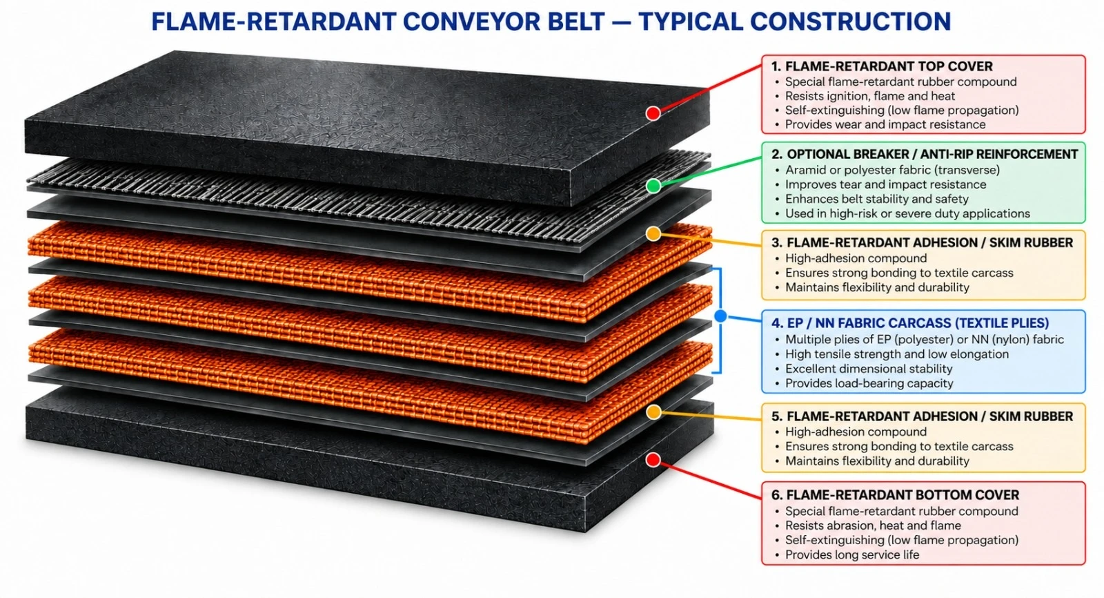
| Component | Engineering Function | Typical Options |
|---|---|---|
| Flame-retardant top cover | Primary conveying surface and fire-performance layer | FR / FRAS / special safety-qualified compound |
| Flame-retardant adhesion / skim rubber | Bonds cover to carcass and transfers dynamic load | High-adhesion flame-retardant system |
| Load-bearing carcass | Carries operating tension | EP fabric, NN fabric or project-specific steel cord |
| Breaker / anti-rip reinforcement | Improves impact and tear resistance | Textile breaker / transverse synthetic or steel reinforcement |
| Flame-retardant bottom cover | Protects pulley-side carcass | FR or FRAS compound |
| Edge construction | Protects reinforcement | Cut edge / moulded edge / engineered edge |
FR-EP Series — Flame-Retardant EP Fabric Conveyor Belt. Low-elongation EP fabric construction for heavy-duty general industrial conveying where flame-retardant performance is specified.
FR-NN Series — Flame-Retardant Nylon Fabric Conveyor Belt. Flexible textile construction for impact-oriented applications requiring flame-retardant cover properties.
FRAS Series — Flame-Retardant & Antistatic Conveyor Belt. Combines controlled flammability with electrical conductivity for static-charge dissipation.
FR-AR Series — Flame-Retardant Anti-Rip Conveyor Belt. Adds breaker or transverse reinforcement for sharp, heavy or penetrating materials.
FR-X Series — Engineered Safety-Critical Conveyor Belt. Project-specific configuration for regulated, underground or special fire-risk environments requiring defined certification or statutory approval.
| Carcass | Characteristics | Typical Application | Engineering Note |
|---|---|---|---|
| EP Fabric | Low elongation, strong dimensional stability | General heavy-duty FR conveying | Versatile standard textile option |
| NN Fabric | High flexibility and impact absorption | Shorter conveyors and impact-oriented duty | Higher elongation than EP |
| High-Strength EP | Higher tensile capacity with low elongation | Longer and heavier FR conveyors | Requires adequate pulley diameter |
| Steel Cord Option | Very high tensile strength and low elongation | High-tension project-specific duty | Separate steel-cord engineering required |
| Cover System | Primary Property | Typical Application |
|---|---|---|
| FR | Flame-retardant | General industrial fire-risk environments |
| FRAS | Flame-retardant + antistatic | Coal handling and dust-sensitive bulk systems |
| Underground / Regulated FR | Special flame and safety performance | Approved underground or regulated installations |
| FR + Abrasion | Fire performance + high wear resistance | Coal, minerals and abrasive bulk materials |
| FR + Anti-Rip | Fire performance + tear propagation control | Sharp or penetrating materials |
Compound selection must evaluate flame performance together with abrasion, temperature, oil contamination, weather exposure and electrical-resistance requirements.
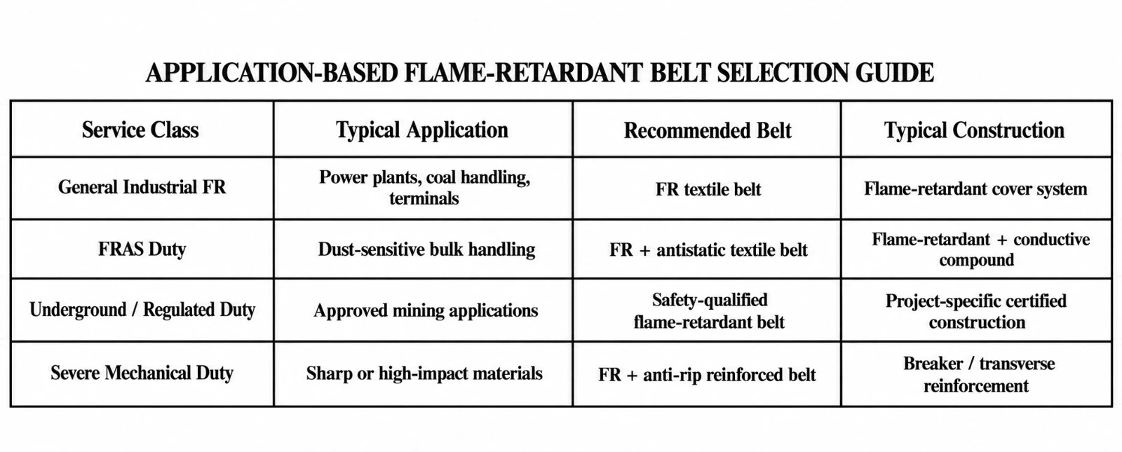
| Configuration | Typical Environment | Key Engineering Focus |
|---|---|---|
| General-use flame-retardant belt | Power plants, coal washeries, ports and surface bulk handling | Flame-retardant cover performance and mechanical strength |
| FRAS general-use belt | Coal and dust-sensitive industrial systems | Flame resistance plus electrical conductivity |
| Underground / regulated flame-retardant belt | Mining or statutory controlled environments | Special fire, antistatic and approval requirements |
| Anti-rip flame-retardant belt | Heavy-duty conveying with piercing risk | Fire performance plus transverse rip protection |
Underground suitability should never be inferred from a general FR designation alone. The exact regulatory approval, test standard and local statutory requirement must be stated in the purchase specification.
| Parameter | Catalogue Option / Range | Remarks |
|---|---|---|
| Belt width | Approx. 400–3,200+ mm | Project-dependent |
| Textile carcass | EP / NN multi-ply | Selected by operating tension |
| Steel cord option | Project-specific ST classes | For high-tension applications |
| Top cover thickness | Typically 4–15+ mm | Selected by wear, impact and fire requirements |
| Bottom cover thickness | Typically 2–8+ mm | Selected by pulley-side duty |
| Cover system | FR / FRAS / regulated FR / engineered | Project-specific safety class |
| Electrical resistance | Antistatic option available | Acceptance criterion must be specified |
| Rip protection | Optional breaker / transverse reinforcement | Recommended for severe mechanical duty |
| Splice method | Hot vulcanized preferred | Matched to carcass construction |
| Property | Typical Engineering Requirement | Remarks |
|---|---|---|
| Cover tensile strength | Project-specific FR compound value | Defined in approved specification |
| Elongation at break | Project-specific | Must remain compatible with dynamic flexing |
| Abrasion resistance | Application-specific | Higher wear resistance for coal/mineral duty |
| Adhesion strength | High cover-to-ply / ply-to-ply bond | Critical to service life |
| Flame behavior | Must meet specified test method and acceptance limit | ISO 340:2022 or project standard |
| Electrical conductivity | Specified for FRAS applications | ISO 284:2025 or approved equivalent |
| Property / Test | Purpose | Current Reference |
|---|---|---|
| Laboratory-scale flammability | Assess reaction to an ignition flame source | ISO 340:2022 |
| Electrical conductivity | Assess static-charge dissipation | ISO 284:2025 |
| Textile belt construction | General construction requirements for textile conveyor belts | ISO 14890:2026 |
| Project-specific underground / mining safety | Define statutory approval and fire-performance criteria | Applicable local regulation / customer specification |
ISO 340:2022 applies to conveyor belts with textile carcasses as well as steel cord conveyor belts and specifies a laboratory-scale method for assessing reaction to an ignition flame source. ISO 284:2025 specifies maximum electrical resistance and the corresponding test method for conductivity.
| Reinforcement | Function | Best Fit |
|---|---|---|
| Textile breaker | Improves impact distribution and local damage control | General heavy-duty FR service |
| Transverse synthetic cord | Improves longitudinal rip resistance | Sharp bulk materials |
| Transverse steel cord | High-strength rip protection | Severe piercing risk |
| Periodic rip-stop zones | Localized damage arrest strategy | Critical long conveyors |
| Electronic rip detection compatibility | Supports early damage detection | High-value conveyor systems |
| Industry | Typical Materials | Primary Requirement |
|---|---|---|
| Coal Handling | Coal and fuel materials | FR / FRAS performance and heavy-duty strength |
| Power Plants | Coal, biomass and fuel handling | Reliable fire-risk control and continuous duty |
| Mining | Ore, coal and bulk minerals | High strength, abrasion and tear resistance |
| Coal Washeries | Processed coal | Flame-retardant general-use textile belt |
| Ports & Terminals | Coal and bulk commodities | High capacity and continuous operation |
| Cement & Minerals | Bulk mineral products | FR + abrasion resistance where required |
| Metallurgy | Raw materials and bulk solids | Heavy-duty flame-retardant conveying |
| Design Factor | Engineering Impact |
|---|---|
| Drive pulley diameter | Controls carcass bending fatigue |
| Tail / bend pulley diameter | Influences reverse bending and belt life |
| Take-up travel | Accommodates elastic stretch and operational movement |
| Drive traction | Depends on belt tension and pulley lagging |
| Belt Speed (m/s) | Influences dynamic load and heat generation |
| Transition distance | Controls edge and carcass stress |
| Fire-risk zoning | Influences cover and safety-system selection |
Flame-retardant conveyor belts should use splice materials compatible with the parent belt and the required fire-performance class. Hot-vulcanized splicing is generally preferred for critical industrial service.
| Inspection Point | What to Check | Recommended Action |
|---|---|---|
| Top cover | Cuts, burning, glazing, cracking or severe wear | Repair and investigate source |
| Edges | Exposed reinforcement or delamination | Immediate repair |
| Splices | Cracking, separation or movement | Engineered inspection |
| Pulley lagging | Slip or heat generation | Restore traction |
| Rip-protection system | Damage or detector malfunction | Repair / test system |
| Grounding / conductivity path | Loose bonding or contamination | Restore electrical continuity |
| Carcass | Exposed fabric or steel reinforcement | Repair or replace |
| Control Item | Purpose | Typical Stage |
|---|---|---|
| Belt width / thickness | Dimensional compliance | Final inspection |
| Carcass verification | Confirm EP / NN / steel cord construction | Production |
| Cover physical properties | Confirm compound consistency | Laboratory |
| Adhesion testing | Verify cover-to-carcass bonding | Laboratory |
| Flammability testing | Verify specified flame performance | Qualification / acceptance |
| Electrical resistance testing | Verify antistatic performance where specified | Qualification / acceptance |
| Visual inspection and traceability | Detect defects and identify production batch | Final / dispatch |
| Reference | Relevance |
|---|---|
| ISO 340:2022 | Conveyor belts — laboratory-scale flammability characteristics — requirements and test method |
| ISO 284:2025 | Conveyor belts — electrical conductivity — specification and test method |
| ISO 14890:2026 | Textile conveyor belts — specification for rubber- or plastics-covered belts for general use |
| ISO 15236 series | Steel cord conveyor belts where steel-cord carcass construction is specified |
| Project / statutory standard | Underground mining, local fire-safety or customer-specific requirements |
The exact standard edition and any local mining or fire-safety approval must be stated in the project specification. General-use flame-retardant belts and underground-approved belts are not automatically interchangeable.
| Project / Site | |
| Industry | |
| Aboveground / Underground / Regulated | |
| Conveyed Material | |
| Capacity (t/h) | |
| Bulk Density | |
| Maximum Lump Size | |
| Belt Width (mm) | |
| Belt Speed (m/s) | |
| Center Distance (m) | |
| Inclination (°) | |
| Required Carcass Type | |
| Required Belt Strength | |
| Top / Bottom Cover (mm) | |
| Required Flame Standard | |
| Antistatic Requirement | |
| Electrical Resistance Criterion | |
| Underground Approval Required? | |
| Anti-Rip Reinforcement Required? | |
| Rip Detection / Monitoring Required? | |
| Drive Pulley Diameter | |
| Tail Pulley Diameter | |
| Take-Up Travel | |
| Splice Requirement | |
| Ambient Temperature | |
| Material Temperature | |
| Applicable Regulation / Standard | |
| Additional Operating Notes |
Low-Temperature Rubber Belt for Freezing, Arctic and Cold-Storage Applications

World Prime Services Cold-Resistant Conveyor Belt is engineered for conveying bulk material in sub-zero environments, where conventional rubber compounds can stiffen, lose elasticity, crack or become vulnerable to impact damage. The product platform uses specially formulated low-temperature rubber covers, combined with textile or steel cord carcasses selected for the required tension, distance and duty.
Typical applications include outdoor conveyors in freezing climates, open-pit mines, coal handling systems, winter ports and terminals, power plants, cold-storage facilities, quarries and long-distance bulk-material systems operating under severe low-temperature exposure.
| Engineering Objective | Operational Benefit |
|---|---|
| Maintain cover flexibility at low temperature | Reduces the risk of cracking and brittle surface failure |
| Maintain impact resistance | Supports reliable loading-point performance under freezing conditions |
| Protect the load-carrying carcass | Helps prevent cold-related cover failure from exposing the reinforcement |
| Low-temperature adhesion system | Supports layer integrity under repeated flexing over pulleys |
| Fabric and steel cord configurations | Allows selection for medium- to long-distance, high-tension duty conveyors |

Rubber becomes progressively stiffer as temperature drops. In severe cold, an unsuitable conveyor belt cover can lose flexibility, develop surface cracking and transfer higher dynamic stress to the carcass and splice. Cold-resistant belts use elastomer systems selected to maintain elasticity and impact behavior at reduced temperatures.
Industry references commonly describe cold-resistant covers using natural rubber (NR) and butadiene rubber (BR)-based blends, due to their low-temperature flexibility and impact characteristics. Extreme-service products are frequently divided into cold-service classes around -45°C and -60°C. Final suitability depends on the actual belt temperature, ambient conditions, wind exposure, material temperature, idle periods and startup method.
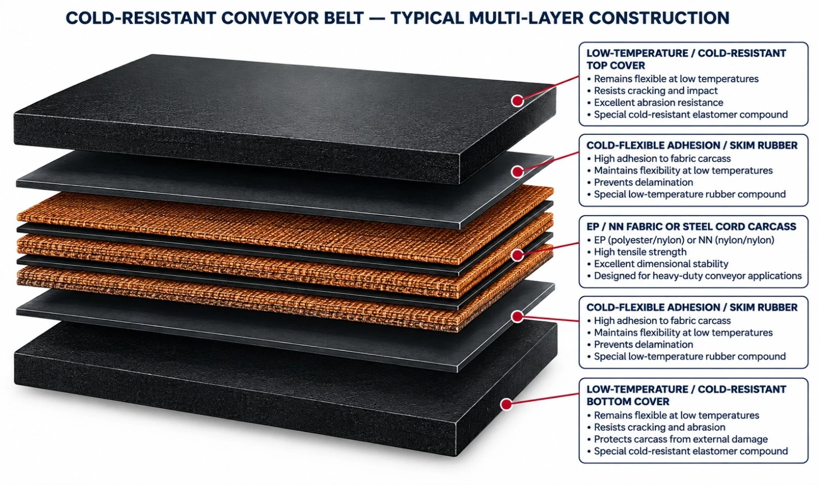
| Component | Engineering Function | Typical Options |
|---|---|---|
| Cold-resistant top cover | Primary wear and impact surface engineered to remain flexible at low temperature | NR/BR-based or dedicated engineered low-temperature compound |
| Cold-flex adhesion / skim rubber | Maintains bonding under repeated flexing in freezing service | Low-temperature compatible adhesion system |
| Tension carcass | Carries longitudinal operating tension | EP fabric, NN fabric or steel cord |
| Cold-resistant bottom cover | Protects the carcass on the pulley side and supports repeated flexing at low temperature | Cold-resistant or combined-service compound |
| Edges | Protects the reinforcement against weathering and moisture penetration | Moulded or cut edge according to construction |
| Series | Description |
|---|---|
| CR-C1-EP | Cold-Resistant EP Fabric Belt — low-elongation EP fabric construction for general severe-winter service, typically selected for outdoor conveying, mines, terminals, quarries and power plants. |
| CR-C2-EP | Extreme-Cold EP Fabric Belt — enhanced low-temperature cover and adhesion system for very severe freezing environments and refrigerated applications. |
| CR-NN | Cold-Resistant Nylon Fabric Belt — flexible, impact-tolerant construction for short- and medium-distance conveyors exposed to low-temperature load impact. |
| CR-ST | Cold-Resistant Steel Cord Belt — high-tensile, low-elongation construction for long-distance, high-capacity and high-tension systems in freezing climates. |
| CR-DUAL | Multi-Property Cold-Resistant Belt — low-temperature performance combined with abrasion, oil, antistatic, flame-retardant or tear-resistant properties, where technically compatible. |
Cold-resistant conveyor belt compounds are formulated to reduce low-temperature hardening and preserve the dynamic properties needed for troughing, pulley flexing, impact absorption and splice reliability. Compound selection must balance cold flexibility with abrasion resistance, tensile properties, aging resistance and the actual conveyed material.
| Compound Family | Primary Performance | Typical Use | Selection Note |
|---|---|---|---|
| C1 Cold Service | Flexibility and impact resistance in severe winter | Outdoor conveyors in cold regions | Typical application envelope around the -45°C class |
| C2 Extreme Cold Service | Maximum low-temperature flexibility | Arctic, cold-storage and extreme-winter service | Typical application envelope around the -60°C class |
| Cold-Resistant + Abrasion | Low-temperature flexibility with enhanced wear resistance | Mining, aggregates, ore and coal | For abrasive bulk materials |
| Cold-Resistant + Oil | Low-temperature flexibility with oil resistance | Oily bulk materials in cold climates | Requires hydrocarbon-specific formulation |
| Cold-Resistant + Flame | Low-temperature flexibility plus flame requirements | Selected regulated coal/mining applications | Applicable safety standard must be specified |
| Cold-Resistant + Tear-Resistant | Cold-resistant covers with transverse reinforcement | Sharp materials in freezing service | Project-specific reinforced construction |
| Carcass | Characteristics | Typical Application | Engineering Consideration |
|---|---|---|---|
| EP Fabric | Low elongation, good dimensional stability and troughability | General heavy-duty conveying in cold climate | Versatile standard textile option |
| NN Fabric | High flexibility and impact absorption | Shorter conveyors and high-impact loading | Higher elongation than EP |
| Steel Cord | Very high tensile strength and very low elongation | Long-distance, high-capacity, high-tension systems | Requires dedicated engineered pulleys and splice |
| Hybrid / Reinforced Tear-Resistant | Additional transverse reinforcement | Sharp or piercing materials in cold environments | Project-specific design |
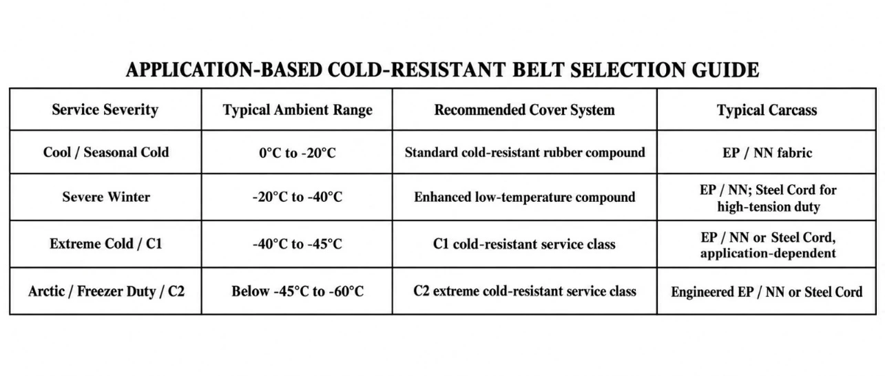
| Service Class | Indicative Ambient Temperature | Typical Application | Important Note |
|---|---|---|---|
| Standard Cold Service | 0°C a -20°C | Seasonal winter operation | Confirm startup conditions and idle period |
| Severe Cold Service | -20°C a -40°C | Mining, terminals and northern stockyards | Low-temperature compound recommended |
| Type C1 Service | Down to approx. -45°C | Severe freezing environments | Industry-common cold-resistance class |
| Type C2 Service | Down to approx. -60°C | Arctic / cold-storage / extreme-cold service | Requires extreme low-temperature compound and full design review |
Temperature classes are indicative engineering categories. The minimum acceptable service temperature must be confirmed in the technical quotation. Belt surface temperature can differ from ambient temperature due to material temperature, friction, solar exposure, wind-chill effect and stoppage duration.
| Parameter | Catalog Option / Range | Selection Basis |
|---|---|---|
| Belt width | 400–3.200 mm | Conveyor design and manufacturing feasibility |
| Textile carcass | EP / NN multi-ply | Operating tension and dynamic load |
| Steel cord carcass | Project-specific ST classes | Long-distance or high-tension service |
| Top cover thickness | Typically 4–20+ mm | Abrasion, impact and minimum temperature |
| Bottom cover thickness | Typically 2–10+ mm | Pulley-side wear and low-temperature flexing |
| Cover system | C1 / C2 / dedicated engineered cold-resistant | Minimum service temperature |
| Edge construction | Moulded or cut edge | Weathering and moisture exposure |
| Splice method | Hot vulcanized preferred for critical service | Carcass and minimum temperature |
| Combined properties | Abrasion / oil / flame / antistatic / tear-resistant | Project-specific compatibility review |
The values below are industry-representative reference values for cold-resistant cover compounds and are included only as an engineering guide. Final guaranteed properties must be stated in the approved product specification.
| Property | Representative Reference | Engineering Meaning |
|---|---|---|
| Tensile strength | ≥ 14 MPa typical general cold-resistant grades; higher-service grades may be specified | Mechanical strength of the cover compound |
| Elongation at break | ≥ 350% typical reference | Deformation capacity before rupture |
| Abrasion loss | ≤ 250 mm³ typical reference; lower values available for abrasion-service grades | Wear resistance |
| Hardness | Approx. 60 ± 5 Shore A typical reference | Balance between flexibility and wear resistance |
| C1 service class | Lower temperature class of approx. -45°C | Severe cold service |
| C2 service class | Lower temperature class of approx. -60°C | Extreme cold service |
Specific values vary by cover grade and standard. For abrasive cold-service applications, stronger H- or D-type cover performance may be specified separately from the low-temperature requirement.
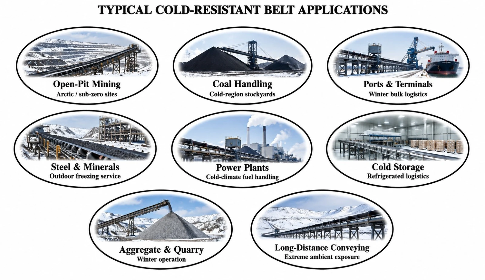
| Industry | Typical Materials | Cold Service Requirement |
|---|---|---|
| Mining | Ore, waste rock, coal | Flexibility and impact resistance during sub-zero operation |
| Coal Handling | Coal and fuel materials | Reliable stockyard and transfer-point performance in winter |
| Ports & Terminals | Ore, coal and bulk cargo | Outdoor operation under frost, snow and wind exposure |
| Power Generation | Coal and biomass | Fuel-handling reliability in cold climate |
| Aggregates & Quarry | Crushed stone and aggregates | Abrasion + cold flexibility |
| Cold Storage / Refrigeration | Packaged or bulk materials | Performance at very low ambient temperature |
| Long-Distance Conveying | Minerals and bulk solids | Low elongation and cold resistance over extended routes |
| Design Factor | Cold-Climate Risk | Engineering Response |
|---|---|---|
| Startup after stoppage | Belt and lubricants may be at minimum ambient temperature | Use suitable belt compound and verify drive startup torque |
| Flexing at pulleys | Stiffened rubber increases flexing stress | Confirm pulley diameters and low-temperature flexibility |
| Frozen material buildup | Can cause tracking problems and impact | Use suitable scrapers, covers and maintenance |
| Ice on idlers | Can cause seizing or abnormal belt loading | Use winterized idlers and inspection program |
| Splice behavior | Low temperature can increase local stress | Use splice materials approved for cold service |
| Wind exposure | Can reduce belt temperature below nominal ambient | Consider open-conveyor exposure in the minimum-temperature design |
| Moisture penetration | Freeze/thaw cycles can damage edges or carcass | Maintain cover and edge integrity |
| Inspection Point | What to Check | Recommended Action |
|---|---|---|
| Top cover | Cold cracking, cuts, brittle zones | Repair early and review temperature suitability |
| Edges | Freeze/thaw damage, separation, exposed reinforcement | Seal and repair before carcass exposure advances |
| Splices | Cracking, lifting or bond separation | Repair using approved cold-service procedure |
| Idlers | Frozen or seized rollers | Replace immediately to prevent friction damage |
| Pulleys | Ice buildup and abnormal slippage | Clean and inspect the lagging |
| Take-up system | Restricted movement due to freezing | Maintain free operation and correct belt tension |
| Control Item | Purpose | Typical Stage |
|---|---|---|
| Belt width and thickness | Confirm dimensional compliance | Final inspection |
| Carcass identification | Confirm ordered reinforcement | Production |
| Cover tensile / elongation | Verify mechanical properties | Laboratory control |
| Abrasion test | Verify wear performance when specified | Laboratory control |
| Low-temperature flexibility / cold-resistance evaluation | Verify performance in the specified class | Laboratory / qualification |
| Adhesion test | Confirm cover-to-carcass bonding | Laboratory control |
| Visual inspection and traceability | Detect defects and identify the production batch | Final inspection / dispatch |
Belt construction and acceptance may be specified per internationally recognized conveyor belt standards, together with project-specific low-temperature requirements. The applicable standard and its edition must be stated in the purchase specification.
| Reference | Relevance |
|---|---|
| ISO 14890 | Textile conveyor belts for general use — construction and mechanical requirements |
| ISO 15236 (série) | Steel cord conveyor belts — design, dimensions and mechanical requirements |
| ISO 37 | Tensile stress-strain properties of rubber |
| ISO 4649 | Rubber abrasion resistance by the rotating cylindrical drum method |
| Project-specific cold-resistance test protocol | Low-temperature flexibility and retained mechanical performance |
A general conveyor-belt construction standard does not by itself guarantee suitability at -45°C or -60°C. The minimum operating temperature and required cold-service class must be explicitly included in the technical purchase specification.
| Project / Site | |
| Industry | |
| Conveyed Material | |
| Minimum Ambient Temperature | |
| Minimum Belt Temperature | |
| Material Temperature | |
| Maximum Lump Size | |
| Bulk Density | |
| Capacity (t/h) | |
| Belt Width (mm) | |
| Belt Speed (m/s) | |
| Center Distance (m) | |
| Inclination (°) | |
| Carcass / Required Strength | |
| Top / Bottom Cover (mm) | |
| Required Cold Service Class | |
| Abrasion Requirement | |
| Oil Resistance Requirement | |
| Flame Resistance Requirement | |
| Antistatic Requirement | |
| Tear-Resistance Requirement | |
| Splice Requirement | |
| Startup After Prolonged Cold Stoppage? | |
| Applicable Standard | |
| Additional Operating Notes |
Heavy-Duty Rubber Belt for Handling Chemically Aggressive Bulk Material
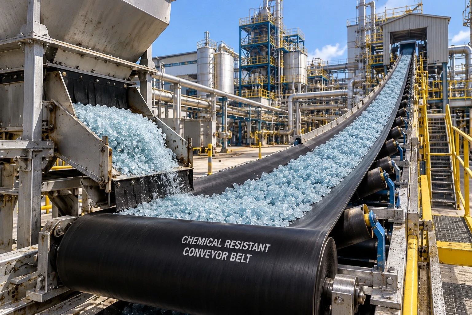
World Prime Services Chemical-Resistant Conveyor Belt is engineered for continuous conveying of bulk material where acids, alkalis, salts, fertilizers, process chemicals or chemically contaminated materials can cause premature degradation of conventional rubber belts.
The product concept combines a chemically resistant cover compound with a compatible adhesion system and a high-strength textile or steel cord carcass. The primary objective is to reduce swelling, softening, hardening, cracking, blistering, loss of adhesion and chemical penetration while maintaining the mechanical properties required for industrial conveying.

Chemical resistance is governed by the interaction between the elastomer, the chemical medium and the operating conditions. Chemical identity alone is not sufficient for belt selection: concentration, temperature, exposure duration, wet or dry contact, mixture composition and mechanical abrasion must all be evaluated.
No single rubber compound is universally resistant to all acids, alkalis, oils, solvents and oxidizing agents. Final selection must therefore be based on real service data and, for severe or unknown media, on laboratory compatibility testing.
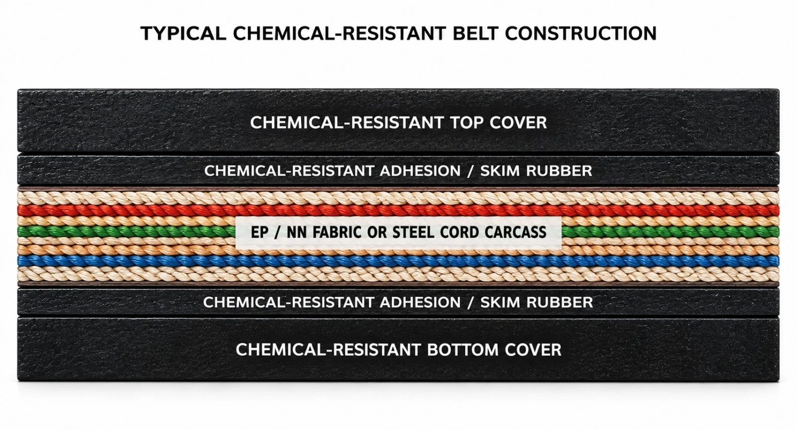
| Component | Engineering Function | Typical Options |
|---|---|---|
| Top cover | Primary chemical barrier and conveying surface | EPDM, NBR, CR or special chemical-resistant formulation |
| Adhesion / skim rubber | Maintains bonding between the cover and the tension member | High-adhesion, chemically compatible compound |
| Tension carcass | Carries longitudinal operating tension | EP fabric, NN fabric or steel cord |
| Bottom cover | Protects the carcass on the pulley side from the environment and chemical contamination | Chemical-resistant or combined-service compound |
| Edges | Reduces lateral penetration into the reinforcement | Moulded edge preferred for severe wet chemical exposure |
| Series | Description |
|---|---|
| CR-EP | EP Fabric Chemical-Resistant Belt — low-elongation polyester/nylon fabric carcass for chemical processing, fertilizers, minerals and general heavy-duty industrial applications. |
| CR-NN | Nylon Fabric Chemical-Resistant Belt — flexible, impact-tolerant construction for short- and medium-distance conveyors handling chemically aggressive bulk materials. |
| CR-ST | Steel Cord Chemical-Resistant Belt — high-tensile, low-elongation construction for long-distance, high-capacity and high-tension systems. Cover chemistry and cord protection are engineered to the service environment. |
| CR-DUAL | Dual-Property Chemical-Resistant Belt — chemical resistance combined with abrasion, heat, oil, antistatic or flame resistance, where technically compatible. |
| CR-X | Severe Chemical Service, Engineered — application-specific construction for severe concentration, elevated temperature, prolonged wet exposure or mixed chemical environments. |
| Compound Family | Typical Performance Profile | Representative Service | Important Limitation |
|---|---|---|---|
| EPDM Base | Strong resistance to many acids, alkalis, hot water, ozone and weathering | Chemical processing, fertilizers, pulp and paper | Generally unsuitable for petroleum oils and many hydrocarbons |
| NBR Base | Strong resistance to oils and many hydrocarbon-bearing media | Oily chemicals, contaminated recycling streams | Compatibility with strong acids/oxidizers must be verified |
| CR / Chloroprene Base | Balanced resistance to weathering, ozone and moderate chemicals | General industrial chemical service | Not universal for strong solvents or concentrated aggressive chemicals |
| Special CSM-Type / Engineered Systems | Broad chemical and weather resistance, depending on formulation | Aggressive industrial environments | Availability and compatibility are formulation-specific |
| Custom Engineered Compound | Optimized for a defined chemical-temperature combination | Critical severe-service applications | Requires full service data and technical validation |
| Carcass | Characteristics | Best Fit | Engineering Consideration |
|---|---|---|---|
| EP Fabric | Low elongation, dimensional stability, good troughability | General chemical conveying | Versatile textile construction |
| NN Fabric | High flexibility and impact absorption | Shorter conveyors with impact loading | Higher elongation than EP |
| Steel Cord | Very high tensile strength and very low elongation | Long-distance, high-capacity conveyors | Requires dedicated splice and pulley design |
| Hybrid / Reinforced | Project-specific protection architecture | Severe chemical + impact/tear service | Engineered per application |
The values below form a catalog engineering envelope. Final dimensions, carcass strength, cover thickness and compound are confirmed in the approved technical quotation.
| Parameter | Catalog Option / Range | Selection Basis |
|---|---|---|
| Belt width | 400–3.200 mm | Conveyor design and manufacturing feasibility |
| Textile construction | EP / NN multi-ply | Operating tension and dynamic load |
| Steel cord construction | Project-specific ST classes | Long-distance / high-tension requirements |
| Top cover | Typically 4–20+ mm | Chemical severity, abrasion and impact |
| Bottom cover | Typically 2–10+ mm | Pulley-side environment |
| Edge construction | Moulded or cut edge | Moulded edge preferred for aggressive wet service |
| Compound | EPDM / NBR / CR / special engineered systems | Chemical compatibility |
| Splice | Hot vulcanized preferred for critical service | Carcass and chemical environment |
| Operating temperature | Compound-dependent | Must be evaluated together with chemical concentration |
| Chemical Environment | Initial Compound Family for Evaluation | Compatibility Note |
|---|---|---|
| Dilute acids | EPDM / CR / dedicated engineered compound | Confirm acid identity, concentration and temperature |
| Strong or oxidizing acids | Special dedicated engineered compound | Laboratory validation strongly recommended |
| Dilute alkalis | Selected EPDM / CR systems | Verify temperature and concentration |
| Hot / concentrated alkalis | EPDM or dedicated engineered system | Elevated temperature materially affects service life |
| Oils and hydrocarbon contamination | NBR base | Verify aromatic content and mixed chemicals |
| Salts / fertilizers | EPDM / CR / dedicated engineered compound | Consider hygroscopic and abrasive effects |
| Solvents | Special chemical-specific compound | No rubber is universally solvent-resistant; validation is required |
| Mixed / proprietary chemicals | Dedicated engineered compound | SDS and full mixture composition are required |
| Industry | Typical Materials / Exposure | Primary Belt Requirement |
|---|---|---|
| Chemical Processing | Acidic, alkaline and salt-bearing solids | Chemical barrier and adhesion retention |
| Fertilizers | Phosphate, potash and fertilizer products | Chemical resistance + abrasion |
| Pulp and Paper | Process chemicals and waste streams | Wet acid/alkali resistance |
| Mining & Mineral Processing | Chemically treated ores and process solids | High strength + chemical resistance |
| Ports & Terminals | Corrosive bulk cargo | Chemical resistance + weathering |
| Wastewater Treatment | Treatment residues and contaminated solids | Wet chemical durability |
| Recycling | Chemically/oil-contaminated materials | Multi-purpose compound selection |
| Combined Requirement | Engineering Approach | Typical Use |
|---|---|---|
| Chemical-Resistant + Abrasion | Chemical-resistant elastomer optimized for wear | Fertilizers, minerals, corrosive granules |
| Chemical-Resistant + Oil | NBR-based or dedicated engineered compound | Oil-contaminated chemical streams |
| Chemical-Resistant + Heat | High-temperature chemical-resistant compound | Hot process materials |
| Chemical-Resistant + Antistatic | Conductive chemical-resistant formulation, where feasible | Selected process industries |
| Chemical-Resistant + Flame | Specially qualified compound system | Regulated applications; standard must be specified |
| Chemical-Resistant + Tear-Resistant | Transverse reinforcement with compatible covers | Chemically aggressive and sharp materials |
| Inspection Point | What to Check | Recommended Response |
|---|---|---|
| Top cover | Swelling, softening, cracking, hardening, blistering | Review chemical compatibility and repair damaged zones |
| Edges | Cuts, separation, exposed reinforcement | Seal or repair before chemical penetration advances |
| Splices | Lifting, cracking, bond degradation | Repair per approved splicing procedure |
| Bottom cover | Chemical contamination or pulley damage | Correct leaks and inspect the carcass |
| Carcass | Exposed fabric or steel cords | Immediate dedicated engineered repair |
| Cleaning system | Chemical incompatibility or excessive pressure | Use compatible cleaning materials and settings |
| Control | Purpose | Stage |
|---|---|---|
| Dimensional inspection | Verify width and cover thickness | Final inspection |
| Carcass identification | Confirm ordered reinforcement | Production |
| Cover physical properties | Confirm compound consistency | Laboratory control |
| Adhesion test | Verify layer integrity | Laboratory control |
| Chemical compatibility / immersion test | Assess property retention after exposure | Project-specific |
| Visual inspection | Detect manufacturing defects | Final inspection |
| Roll traceability | Link the product to the manufacturing batch | Dispatch |
For severe applications, compatibility programs may compare mass or volume change, hardness, tensile strength, elongation and visual condition before and after controlled chemical exposure.
| Reference | Relevance |
|---|---|
| ISO 14890:2026 | Rubber- or plastics-covered textile conveyor belts for general use |
| ISO 15236-1:2016 | Steel cord conveyor belts — design, dimensions and mechanical requirements for general use |
| Project-specific chemical compatibility protocol | Evaluation of the selected cover compound against the actual service medium |
The general conveyor-belt construction standard does not by itself certify compatibility with a specific chemical. Chemical resistance must be defined by the selected compound and validated against the actual operating medium.
| Project / Site | |
| Industry | |
| Conveyed Material | |
| Exact Chemical / Mixture | |
| Chemical Concentration | |
| SDS Available | |
| Material Temperature | |
| Ambient Temperature | |
| Exposure: Dry / Wet / Slurry | |
| Bulk Density | |
| Maximum Lump Size | |
| Capacity (t/h) | |
| Belt Width (mm) | |
| Belt Speed (m/s) | |
| Center Distance (m) | |
| Inclination (°) | |
| Carcass / Required Strength | |
| Top / Bottom Cover (mm) | |
| Preferred Edge Type | |
| Splice Requirement | |
| Combined Property Requirement | |
| Applicable Standard | |
| Additional Notes |
Fabric & Steel Cord Reinforced Solutions
High impact • puncture • longitudinal rip protection
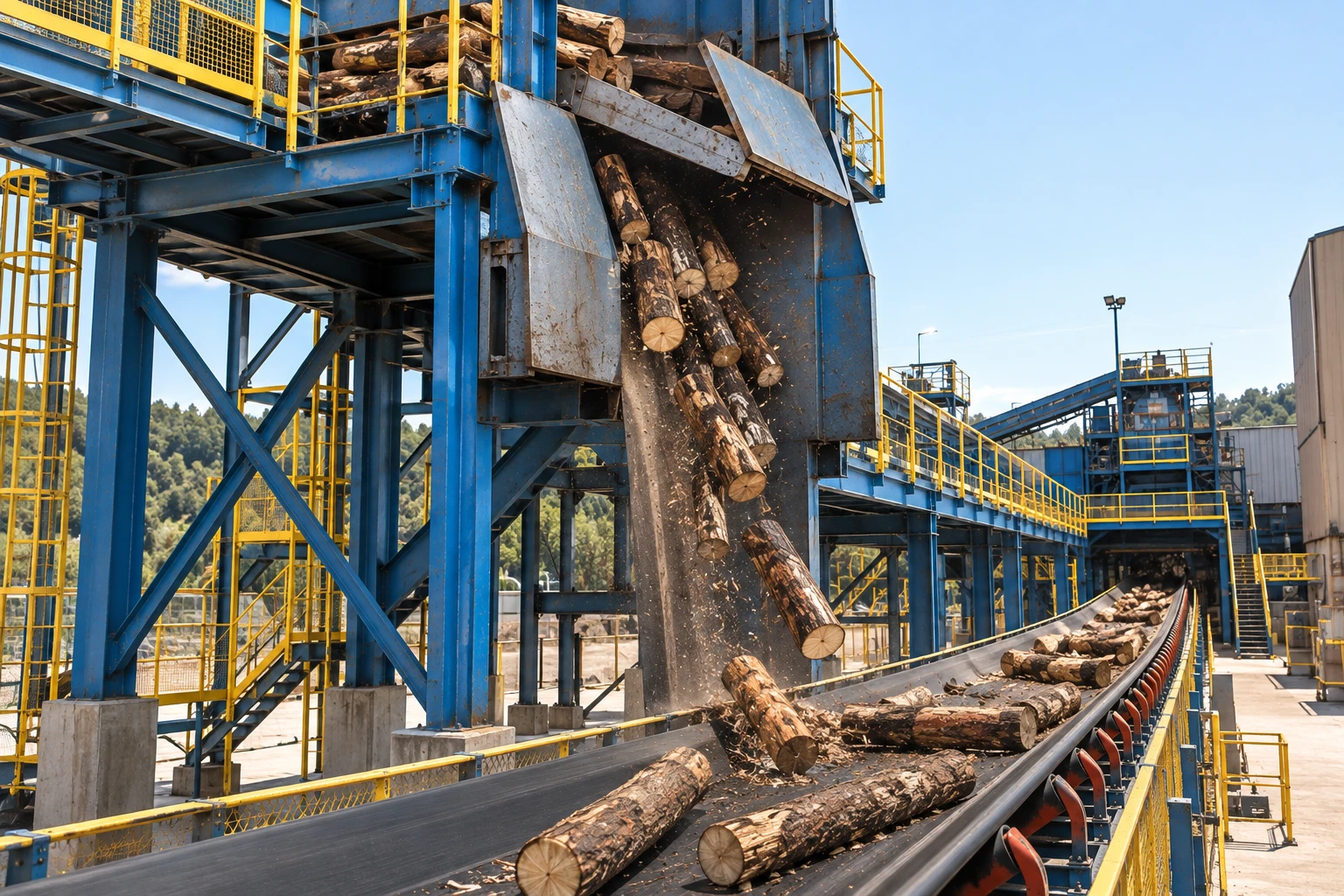
World Prime Services Anti-Tear / Anti-Cut Rubber Conveyor Belts are engineered for conveyors exposed to hard, sharp and irregular materials, high drop heights, impact loading and foreign-object penetration. The range combines a load-bearing textile or steel-cord carcass with a transverse rip-stop reinforcement positioned perpendicular to belt travel.
The transverse reinforcement is intended to resist piercing and to restrict a local puncture from propagating into a long longitudinal tear. The fabric-reinforced and steel-cord anti-tear designs are intended for mines, ports, power, metallurgy, chemical industry and coal handling.
| Industry | Typical Duty / Risk |
|---|---|
| Mining & Quarrying | Sharp rock, ore, overburden, tramp metal |
| Ports & Terminals | Ore, coal, aggregates, foreign objects |
| Steel & Metallurgy | Ore, coke, scrap-contaminated bulk |
| Power & Coal | Coal and stone at severe transfer points |
| Cement | Limestone, clinker, high-impact loading |
| Chemical / Bulk | Hard or sharp solids with puncture risk |
The main longitudinal carcass carries conveyor tension. A separate transverse reinforcement is embedded in the top cover, or in both top and bottom cover zones. Its orientation is approximately 90° to belt travel. During penetration, the transverse layer spreads the local load across the belt width and increases resistance to continued longitudinal tearing.
| Damage Event | Conventional Belt Risk | Anti-Tear Response |
|---|---|---|
| Sharp lump impact | Cover cut / puncture | Breaker absorbs and distributes local load |
| Trapped foreign object | Longitudinal tear propagation | Transverse reinforcement restrains propagation |
| High drop height | Concentrated impact stress | Breaker works with thick cover and impact support |
| Return-side penetration | Underside carcass damage | Optional lower breaker protects from below |
| Layer | Fabric Anti-Tear | Steel Cord Anti-Tear |
|---|---|---|
| Top cover | Cut / abrasion resistant rubber | Cut / abrasion resistant rubber |
| Rip-stop layer | Polyester or nylon canvas / cord | Transverse steel or polyester cords |
| Main carcass | EP / NN textile carcass | Longitudinal steel cords |
| Optional lower breaker | Fabric reinforcement | Steel / polyester reinforcement |
| Bottom cover | Rubber cover | Rubber cover |
The fabric anti-tear belt is suitable for hard and sharp materials at larger drop heights. Highly extensible transverse polyester or nylon canvas is evenly arranged in the top cover, or in both top and bottom cover zones. The anti-tear layer is perpendicular to belt running direction.
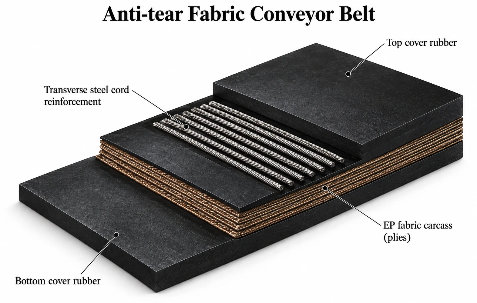
| Parameter | Engineering Options |
|---|---|
| Main carcass | EP or NN textile carcass |
| Transverse reinforcement | Highly extensible polyester or nylon fabric / cord |
| Reinforcement position | Top; or top + bottom |
| Cover | Abrasion / cut / impact resistant rubber |
| Edge | Cut edge or moulded edge |
| Width | Project-specific; reference breaker products commonly 500–2100 mm |
| Customization | Belt rating, ply count, cover thickness, reinforcement density |
For long-distance, high-tension and high-capacity conveyors, the anti-tear steel-cord construction uses longitudinal steel cords as the principal tension member. The design specifies highly extensible transverse steel cords or polyester cords in the top cover, or in both top and bottom cover zones.
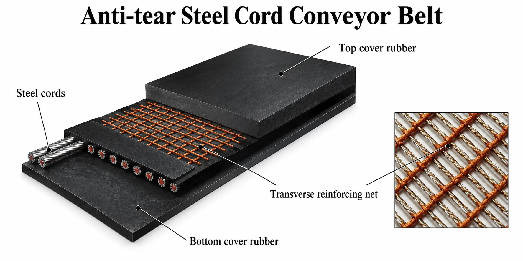
| Use | Reason for Steel Cord Anti-Tear |
|---|---|
| Long overland conveyors | Low elongation and high belt rating |
| High-capacity mining | High tensile demand and severe loading |
| Steep / deep lift systems | High operating tension |
| Severe transfer points | High puncture and impact risk |
| Critical production conveyors | High consequence of longitudinal ripping |
| Reinforcement | Position | Primary Function | Characteristics |
|---|---|---|---|
| Polyester fabric breaker | Top / Top+Bottom | Rip-stop / impact distribution | Flexible, economical, good troughability |
| Nylon fabric breaker | Top / Top+Bottom | Impact absorption / rip-stop | High elongation and energy absorption |
| Polyester transverse cord | Top / Top+Bottom | Localized rip resistance | Flexible cord reinforcement |
| Steel cord breaker | Top / Top+Bottom | Maximum puncture / rip restraint | Highest penetration resistance |
Fabric breakers are generally selected when flexibility and troughability are dominant. Steel transverse reinforcement is favored where sharp foreign objects, severe lump impact or high puncture risk justify a stronger rip-stop layer. Selection must also consider pulley diameters, trough transition, splice design, belt thickness and impact-support systems.
| Grade | Strength N/mm | Pitch mm | Cord Ø mm | Min. Cover mm | Width mm |
|---|---|---|---|---|---|
| ST630 | 630 | 10 | 3.0 | 4.0 | 800–2400 |
| ST800 | 800 | 10 | 3.5 | 4.0 | 800–2400 |
| ST1000 | 1000 | 12 | 4.0 | 4.0 | 800–2400 |
| ST1250 | 1250 | 12 | 4.5 | 4.0 | 800–2400 |
| ST1600 | 1600 | 12 | 5.0 | 4.0 | 800–2400 |
| ST2000 | 2000 | 12 | 6.0 | 4.0 | 800–2400 |
| ST2500 | 2500 | 15 | 7.2 | 5.0 | 800–2400 |
| ST3150 | 3150 | 15 | 8.1 | 5.5 | 800–2400 |
| ST3500 | 3500 | 15 | 8.6 | 6.0 | 800–2400 |
| ST4000 | 4000 | 15 | 8.9 | 6.5 | 800–2400 |
| ST4500 | 4500 | 16 | 9.7 | 7.0 | 800–2400 |
| ST5000 | 5000 | 17 | 10.9 | 7.5 | 800–2400 |
| ST5400 | 5400 | 17 | 11.3 | 8.0 | 800–2400 |
| ST6300 | 6300 | 19.5 | 12.8 | 10.0 | 800–2400 |
| ST7000 | 7000 | 19.5 | 13.5 | 10.0 | 800–2400 |
| ST7500 | 7500 | 21 | 15.0 | 10.0 | 800–2400 |
Reference values cross-checked against published anti-tear steel-cord specification tables. Final manufacturing data must be confirmed on the approved project data sheet.
| Type | Transverse N/mm | Elong. % | Weft Pitch | Yarn N | Thk. mm | Width mm |
|---|---|---|---|---|---|---|
| NN60 | 60 | ≥10 | 8 / 10 cm | 600 | 2.5 | 500–2100 |
| NN80 | 80 | ≥10 | 7 / 10 cm | 600 | 2.5 | 500–2100 |
| NN100 | 100 | ≥10 | 10 / 10 cm | 1050 | 3.0 | 500–2100 |
| NN120 | 120 | ≥10 | 8 / 10 cm | 1050 | 3.0 | 500–2100 |
| NN140 | 140 | ≥10 | 7 / 10 cm | 1050 | 3.0 | 500–2100 |
| EE50 | 60 | ≥10 | 8 / 10 cm | 550 | 2.7 | 500–2100 |
| EE70 | 80 | ≥10 | 7 / 10 cm | 550 | 2.7 | 500–2100 |
| EE90 | 100 | ≥10 | 10 / 10 cm | 1000 | 3.2 | 500–2100 |
| EE110 | 120 | ≥10 | 8 / 10 cm | 1000 | 3.2 | 500–2100 |
| EE130 | 140 | ≥10 | 7 / 10 cm | 1000 | 3.2 | 500–2100 |
| Type | Reference Options |
|---|---|
| Steel cord | 0.65 / 1.20 / 1.38 / 1.52 / 1.82 / 2.00 mm diameters |
| Polyester | Transverse breaker fabric / cord |
| Nylon | Transverse breaker fabric / cord |
The standard states that cover grades are selected in accordance with ISO 15236. Published values help select a cover compound, but tensile strength and abrasion values alone cannot reliably predict actual wear and cut resistance in service.
| Grade | Tensile Strength Min. | Elongation at Break Min. | Abrasion Max. | Typical Emphasis |
|---|---|---|---|---|
| H | 24 MPa | 450% | 120 mm³ | High tensile / severe duty |
| D | 18 MPa | 400% | 100 mm³ | High abrasion resistance |
| L | 15 MPa | 350% | 200 mm³ | General duty |
| Ka | 15 MPa | 350% | 200 mm³ | Flame-resistant / antistatic when specified |
Ka is associated in published references with flame resistance and antistatic performance under ISO 340 and ISO 284. Contract requirements and current standard editions must be confirmed at order stage.
E = m × g × h
E = impact energy (J); m = representative lump mass (kg); g = 9.81 m/s²; h = effective free-fall height (m). Use for transfer-severity comparison, not as a stand-alone belt design rule.
U = T_operating / T_rated
The allowable utilization depends on the governing standard, splice efficiency and manufacturer design practice.
n ≈ (B − 2e) / p
n = approximate cord count; B = belt width; e = edge margin; p = cord pitch. Actual cord count is manufacturer-specific.
| Material / Duty | Impact | Puncture | Rip | Recommended Reinforcement |
|---|---|---|---|---|
| Large hard rock | High | High | High | Steel transverse reinforcement |
| Iron ore / sharp ore | High | High | High | Steel or heavy polyester cord |
| Coal with tramp metal | Medium | High | High | Steel breaker + optional rip detection |
| Limestone / raw cement | Med–High | Med–High | Med–High | Fabric or steel by lump size |
| Coke / metallurgy | Medium | Med–High | Medium | Fabric/cord breaker + selected cover |
| General bulk solids | Low–Med | Low–Med | Low–Med | Fabric breaker where justified |
Anti-tear reinforcement changes the belt construction around the splice and must be incorporated into the approved manufacturer splice procedure. Steel-cord splice design must match belt rating, cord diameter, cord pitch, cover thickness and splice length.
| Item | Recommended Practice |
|---|---|
| Splice | Hot vulcanized splice for critical heavy-duty service |
| Breaker termination | Manufacturer-approved stagger / termination geometry |
| Loading zone | Correct chute trajectory plus adequate impact beds/idlers |
| Scrapers | Avoid sharp cleaner edges and excessive pressure |
| Inspection | Routine cover, edge, splice and rip-stop checks |
| Steel cord inspection | Approved NDT / X-ray / magnetic methods where required |
| Rip detection | Consider sensor-loop or intelligent monitoring for critical systems |
Anti-tear construction reduces the probability and propagation of ripping; it does not replace correct chute design, impact support, housekeeping or foreign-object control.
| Required Data | Example / Requirement |
|---|---|
| Belt type | Anti-Tear Fabric / Anti-Tear Steel Cord |
| Belt rating | EP800/4 or ST2000 |
| Width | 1,600 mm |
| Top / bottom cover | 10 + 5 mm |
| Cover grade | H / D / L / Ka or contract grade |
| Rip-stop position | Top / Top + Bottom |
| Transverse reinforcement | Type, diameter, pitch or fabric grade |
| Material | Iron ore / rock / coal / limestone etc. |
| Max. lump size | Project value |
| Drop height | Project value |
| Belt speed | m/s |
| Capacity | t/h |
| Trough angle | 20° / 30° / 35° / 45° |
| Pulley diameters | Drive / tail / bend / take-up |
| Splice | Hot vulcanized |
| Special requirements | Flame / heat / oil / cold / antistatic / rip detection |
ANTI-TEAR ST2000 / 1600 mm / 10+5 mm / STEEL TRANSVERSE BREAKER TOP / D COVER / MOULDED EDGE
Application-Specific Belt for Pine, Timber, Wood Chips, Bark and Resin-Contaminated Bulk Materials
ENGINEERED TECHNICAL CATALOGUE
NBR-based cover concept • EP textile carcass • Resin / pine-oil / turpentine exposure control
| Primary duty | Forestry, sawmills, pulp & paper, wood-chip and bark handling |
| Design basis | Oil/solvent-resistant rubber technology adapted to pine-resin exposure |
| Validation basis | ISO 1817 liquid-immersion testing with actual customer resin/process fluid |

Pine resin is not a single standardized test liquid. Fresh pine exudate can contain rosin/resin acids together with volatile terpene fractions; process contamination may also include pine oil, turpentine-like components, lubricants, heat and wood extractives. For that reason, a belt described as “pine-resin resistant” should be treated as an application-specific chemical-resistance specification rather than as a universal DIN cover grade.
The recommended industrial starting point is a high-acrylonitrile NBR-based cover compound, optionally blended and reinforced for abrasion, flex-fatigue and adhesion. NBR is widely used for oil-resistant conveyor covers and is generally more compatible with turpentine/pine-oil type exposure than NR, SBR or EPDM. Final acceptance must be based on immersion testing using the actual resin or representative process liquid at the real operating temperature.
| Designation | Recommended Description |
|---|---|
| PRR-NBR | Pine Resin Resistant – NBR Cover |
| PRR-NBR-H | Pine Resin Resistant – NBR Cover, elevated-temperature formulation |
| PRR-FKM-X | Special fluorocarbon-rich cover concept for unusually aggressive solvent/terpene exposure; engineering review required |
| Exposure Mechanism | Possible Belt Effect | Engineering Response |
|---|---|---|
| Resin / terpene absorption | Cover swelling, softening, dimensional change | Use NBR-rich cover; verify volume change by immersion test |
| Sticky rosin deposits | Material carryback, surface fouling | Smooth dense cover, effective scrapers and cleaning plan |
| Wood chips / bark abrasion | Cutting, gouging, cover loss | Higher tear/abrasion resistance and adequate top-cover thickness |
| Heat + resin | Accelerated ageing and extraction | Select temperature-rated compound and test at service temperature |
| Solvent-rich process streams | Rapid elastomer attack | Escalate to special compound; consider FKM-rich solution after compatibility testing |
| Property | Recommended Engineering Target | Comment |
|---|---|---|
| Base polymer | High-acrylonitrile NBR or NBR-rich blend | Preferred starting point for pine oil / turpentine / resinous exposure |
| Cover tensile strength | ≥ 15 MPa target | Comparable to robust oil-resistant cover grades |
| Elongation at break | ≥ 350% target | Supports flexing and impact duty |
| Abrasion loss | ≤ 150–200 mm³ target | Select according to chip/bark abrasiveness |
| Hardness | 60–70 Shore A typical target | Balance between cut resistance and flexibility |
| Static conductivity | Available when required | Specify ISO 284 compliance if electrostatic control is required |
| Top cover | 4–10 mm typical | Duty dependent; heavy wood chips generally require thicker cover |
| Bottom cover | 2–4 mm typical | Adjust to pulley/idler duty |
Important: the numerical values above are recommended procurement/design targets, not a claim that a universal international “pine resin” conveyor-belt grade exists. The compound must be qualified against the actual resin/process medium.
| Test | Recommended Requirement |
|---|---|
| Primary method | ISO 1817:2026 – evaluate changes in rubber properties before and after immersion in liquids |
| Customer-specific liquid | Actual pine resin, condensate, pine oil, turpentine-containing fluid, or representative mixture |
| Temperature points | 23°C minimum; add actual service temperature (e.g. 50°C / 70°C / higher if applicable) |
| Exposure periods | 24 h, 72 h and 168 h recommended engineering screening sequence |
| Volume change | Target ≤ +15% preferred; ≤ +25% may be conditionally acceptable after mechanical-property review |
| Mass change | Record and trend; no uncontrolled extraction or excessive uptake |
| Hardness change | Target within ±10 Shore A |
| Tensile retention | Target ≥ 80% of original |
| Elongation retention | Target ≥ 70% of original |
| Visual condition | No blistering, cracking, delamination, tacky breakdown or severe softening |
| Component | Recommended Construction |
|---|---|
| Top cover | Pine-resin-resistant NBR-based rubber |
| Skim / adhesion layer | High-adhesion rubber compatible with selected NBR cover |
| Carcass | EP (polyester warp / nylon weft) textile carcass |
| Ply range | 2–6 plies, selected by belt rating and pulley geometry |
| Bottom cover | NBR-rich or compatible abrasion-resistant rubber depending on contamination risk |
| Edges | Moulded edge preferred where resin ingress into carcass is a concern |
| Belt Rating | Typical Ply Options | Typical Use |
|---|---|---|
| EP 250–400 N/mm | 2–3 ply | Light wood products, sawdust, short conveyors |
| EP 500–630 N/mm | 3–4 ply | General sawmill, bark and wood-chip duty |
| EP 800–1000 N/mm | 4–5 ply | Heavy wood chips, long conveyors, higher tension |
| EP 1250–1600 N/mm | 5–6 ply | High-tension or demanding industrial service |
| EP 2000+ N/mm | Engineered | Special long/high-capacity conveyors; pulley and splice review required |
| Parameter | Catalogue Range / Recommendation |
|---|---|
| Width | 500–2,400 mm standard engineering range; wider belts by project review |
| Top cover | 3–12 mm |
| Bottom cover | 1.5–6 mm |
| Total belt thickness | Project-specific according to carcass and covers |
| Edge type | Cut edge or moulded edge; moulded preferred for aggressive resin exposure |
| Surface | Smooth standard; special profiles by application |
| Splicing | Hot vulcanized splice preferred for continuous heavy-duty service |
| Grade Concept | Recommended Working Range | Use |
|---|---|---|
| PRR-NBR | Approx. -20°C to +70°C | Normal pine, wood-chip, bark and resin duty |
| PRR-NBR-H | Approx. -20°C to +100°C | Warmer process streams; compound must be heat-aged and immersion-tested |
| PRR-FKM-X | Project-specific | Severe terpene/solvent exposure or elevated temperature; special cost/adhesion review |
Temperature and chemical resistance interact. A compound that performs well at room temperature may swell or lose properties faster at elevated temperature. Qualification testing must therefore reproduce the maximum credible belt-contact temperature.
| Characteristic | Proposed Specification |
|---|---|
| Cover polymer | High-acrylonitrile NBR-based |
| Tensile strength | ≥ 15 MPa |
| Elongation at break | ≥ 350% |
| Abrasion loss | ≤ 150–200 mm³ |
| Cover-to-ply adhesion | ≥ 4.5 N/mm for cover >1.5 mm target |
| Ply-to-ply adhesion | ≥ 5.0 N/mm target |
| Full-thickness elongation | According to selected ISO 14890 belt construction |
| Resin immersion | Pass project-specific ISO 1817 protocol |
| Electrical conductivity | ISO 284 when specified |
| Carcass | EP, low elongation, 2–6 ply |
NBR-Based Industrial Rubber Belting for Oily, Greasy & Hydrocarbon-Contaminated Bulk Material Handling
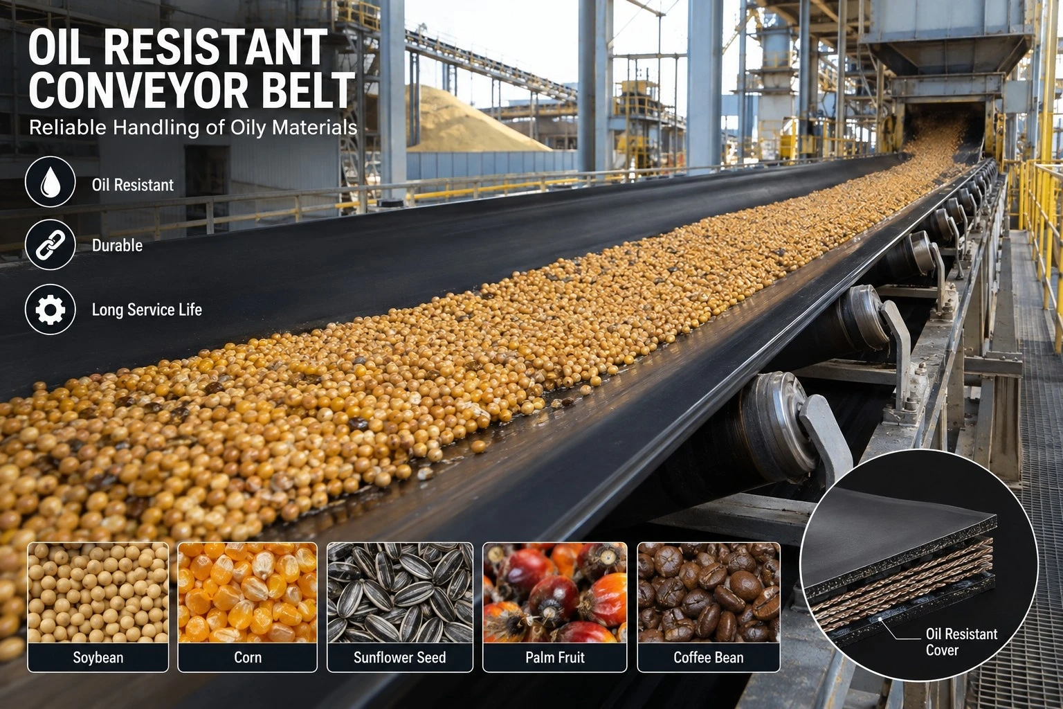
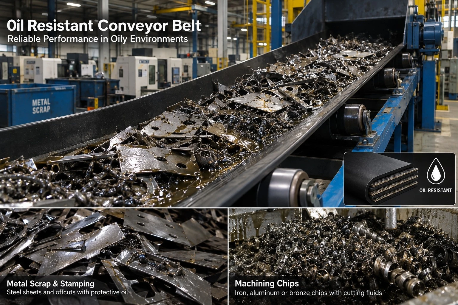
World Prime Services Oil-Resistant Conveyor Belt is engineered for conveying bulk materials containing mineral oils, lubricants, greases, vegetable oils, animal fats and selected hydrocarbon contaminants that can prematurely degrade conventional rubber conveyor-belt covers.
The product family uses nitrile-butadiene rubber (NBR) or engineered oil-resistant rubber compounds as the primary cover system. The objective is to reduce oil-induced swelling, softening, loss of tensile properties, surface tackiness, cover cracking and deterioration of cover-to-carcass adhesion.
The range can be engineered in EP or NN fabric constructions for general industrial service and in steel cord construction for long-distance, high-tension or high-capacity systems.
| Engineering Objective | Operational Benefit |
|---|---|
| Resistance to oil-induced swelling | Helps maintain belt geometry and cover thickness |
| Controlled compound softening | Supports stable tracking and cleaner performance |
| High cover-to-carcass adhesion | Reduces risk of delamination in oily environments |
| NBR-based cover chemistry | Provides improved resistance to mineral oils and hydrocarbons |
| Fabric and steel cord options | Supports medium-duty through high-tension conveying |
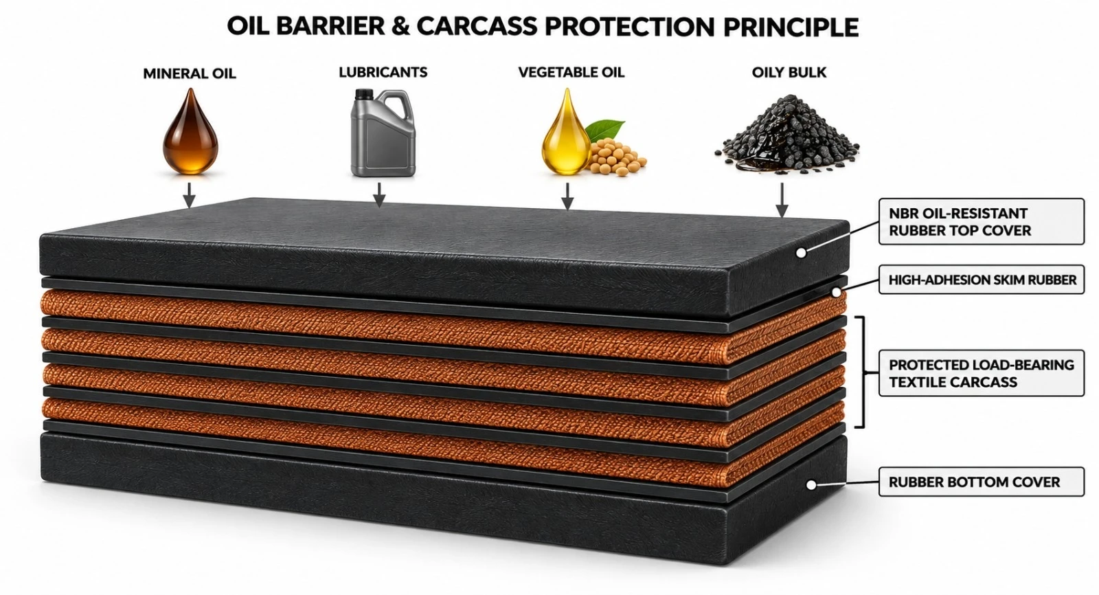
Oils and hydrocarbon liquids can diffuse into conventional rubber compounds, causing volume increase, loss of hardness, surface softening and reduced mechanical strength. In severe cases, oil can also affect adhesion between the cover and reinforcement.
Oil-resistant conveyor belts use specially selected elastomers and compounding systems that limit absorption and preserve useful physical properties under defined exposure conditions. NBR is widely used because of its strong resistance to many mineral oils, lubricants and hydrocarbon-based products.
No single oil-resistant compound is universally compatible with all oils, fuels, solvents or chemicals. Final selection must consider the exact oil type, aromatic content, concentration, temperature and contact duration.
NBR — nitrile-butadiene rubber — is the principal elastomer family used for many industrial oil-resistant conveyor-belt covers. The acrylonitrile content and complete compound formulation influence oil resistance, flexibility, low-temperature behavior, abrasion resistance and processing characteristics.
| NBR Engineering Characteristic | Effect on Conveyor Belt Performance |
|---|---|
| Oil and fuel resistance | Reduces swelling and softening caused by many petroleum-based oils |
| Good abrasion potential | Supports use with oily abrasive bulk materials |
| Strong mechanical properties | Maintains cover integrity under dynamic belt flexing |
| Compound flexibility | Allows optimization for different oil and temperature conditions |
| Compatibility with fabric / steel cord carcasses | Supports a wide range of belt constructions |
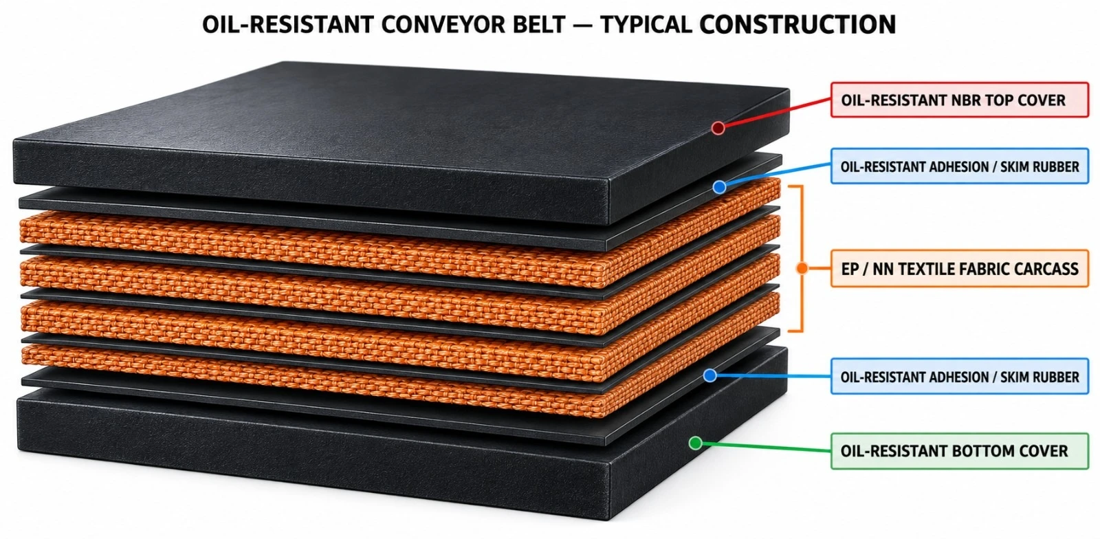
| Component | Engineering Function | Typical Option |
|---|---|---|
| Oil-resistant top cover | Primary barrier against oil-contaminated conveyed material | NBR / engineered oil-resistant compound |
| Oil-resistant skim rubber | Supports adhesion and limits oil migration toward carcass | Compatible high-adhesion compound |
| Load-bearing carcass | Carries operating tension | EP fabric / NN fabric / steel cord |
| Oil-resistant bottom cover | Protects pulley-side reinforcement | NBR or engineered compound |
| Edge construction | Protects reinforcement from side ingress | Cut edge / moulded edge |
OR-EP Series — Oil-Resistant EP Fabric Conveyor Belt. Low-elongation EP carcass for general and heavy-duty oily bulk-material conveying.
OR-NN Series — Oil-Resistant Nylon Fabric Conveyor Belt. Flexible, impact-tolerant construction for medium-duty and impact-oriented service.
OR-ST Series — Oil-Resistant Steel Cord Conveyor Belt. High-tensile, low-elongation belt for long-distance and high-capacity applications.
OR-AR Series — Oil & Abrasion Resistant Belt. Optimized for oily materials that are also abrasive.
OR-H Series — Oil & Moderate Heat Resistant Belt. Engineered for applications combining oil exposure with elevated temperature.
OR-X Series — Engineered Severe Oil Duty. Project-specific compound selection for high oil concentration, elevated temperature or prolonged contact.
| Carcass | Key Characteristics | Typical Use | Engineering Note |
|---|---|---|---|
| EP Fabric | Low elongation and good dimensional stability | General industrial and heavy-duty oil service | Preferred for stable running length |
| NN Fabric | High flexibility and impact absorption | Shorter conveyors and impact-oriented duty | Higher elongation than EP |
| High-Strength EP | Higher tensile capacity | Longer and heavier fabric-belt systems | Requires adequate pulley diameter |
| Reinforced Textile | Special multi-layer construction | Severe impact or anti-rip service | Project-specific |
Oil-resistant steel cord conveyor belts combine NBR-based or engineered oil-resistant covers with a galvanized steel cord tension carcass. This construction is selected where high tensile strength, low elongation and long-distance conveying are required.
| Design Element | Engineering Function |
|---|---|
| Longitudinal steel cords | Provide high tensile strength and low elongation |
| Oil-resistant top cover | Protects belt against oily conveyed material |
| Oil-resistant skim rubber | Supports cord adhesion and limits oil penetration |
| Oil-resistant bottom cover | Protects pulley-side belt structure |
| Optional rip protection | Provides additional protection against longitudinal tearing |
| Exposure Category | Typical Material / Contaminant | Selection Focus |
|---|---|---|
| Light Oil Exposure | Occasional lubricant contamination | General oil-resistant cover |
| Moderate Oil Exposure | Oily grains, recycling materials, machine residues | NBR cover with good abrasion resistance |
| Heavy Mineral Oil Exposure | Petroleum-based oils and lubricants | High oil-resistance NBR compound |
| Vegetable / Animal Oils | Oilseed products and food-processing by-products | Application-specific oil-resistant compound |
| Oil + Abrasion | Oily scrap, recycling and mineral materials | Oil-resistant + abrasion-resistant cover |
| Oil + Heat | Warm oily bulk materials | Dual-property oil/heat-resistant engineered compound |
Oil resistance must be evaluated against the actual service medium. Mineral oil, hydraulic oil, lubricants, vegetable oils and animal fats can affect rubber differently. Aromatic hydrocarbon content and elevated temperature can significantly increase rubber swelling.
| Required Application Data | Why It Matters |
|---|---|
| Exact oil or grease type | Determines compound compatibility |
| Oil concentration | Defines severity of exposure |
| Aromatic content | Can strongly influence swelling behavior |
| Material temperature | Higher temperature accelerates oil diffusion |
| Contact duration | Long exposure increases absorption |
| Bulk material abrasiveness | Determines simultaneous wear requirement |
| Cleaning agents / solvents | May introduce secondary chemical attack |
| Parameter | Catalogue Option / Range | Remarks |
|---|---|---|
| Belt width | Approx. 300–3,200+ mm | Project-dependent |
| Fabric carcass | EP / NN multi-ply | Selected by operating tension |
| Steel cord carcass | Project-specific ST classes | For long-distance / high-tension duty |
| Top cover thickness | Typically 3–20+ mm | Oil severity, abrasion and impact dependent |
| Bottom cover thickness | Typically 1.5–10+ mm | Pulley-side duty dependent |
| Cover compound | NBR / engineered oil-resistant blend | Application-specific |
| Edge construction | Cut edge / moulded edge | Project-specific |
| Splice method | Hot vulcanized preferred | Use compatible oil-resistant splice materials |
| Compound Family | Primary Duty | Typical Application |
|---|---|---|
| OR-G | General oil resistance | Light to moderate oil exposure |
| OR-M | Mineral oil resistance | Lubricants and oily industrial bulk materials |
| OR-AR | Oil + abrasion resistance | Recycling, oily minerals and contaminated bulk |
| OR-V | Vegetable / animal oil service | Oilseed, food and agricultural by-products |
| OR-H | Oil + moderate heat resistance | Warm oily materials |
| OR-X | Severe engineered oil duty | High concentration or prolonged oil exposure |
| Industry | Typical Material | Primary Requirement |
|---|---|---|
| Recycling | Oil-contaminated scrap and processed materials | Oil + abrasion resistance |
| Metal Processing | Oily metal parts, chips and residues | Mineral oil resistance and durability |
| Automotive / Manufacturing | Lubricated components and industrial residues | Stable performance under oil contamination |
| Agriculture / Oilseed | Oil-rich seeds and by-products | Vegetable-oil-resistant compound |
| Ports & Bulk Terminals | Oily bulk cargo | Continuous-duty oil-resistant belting |
| Chemical / Process Industry | Selected oil-containing bulk materials | Application-specific compatibility |
| Duty | Oil Exposure | Recommended Belt | Typical Construction |
|---|---|---|---|
| Moderate | Occasional oil contamination | OR-G EP / NN | General NBR cover |
| High | Continuous mineral-oil contact | OR-M EP / NN | Enhanced NBR cover |
| Severe | Oil + abrasion / impact | OR-AR | Thicker oil/abrasion-resistant top cover |
| High Tension | Oil exposure + long distance | OR-ST | Steel cord + oil-resistant cover system |
| Special | Oil + heat / special chemistry | OR-H / OR-X | Project-specific engineered compound |
Elevated temperature can accelerate oil absorption and increase compound swelling. A belt that performs well with a particular oil at ambient temperature may require a different compound when the conveyed material is warm or hot.
For this reason, both oil type and temperature must be declared during belt selection. Dual-property oil-and-heat-resistant constructions should be validated against the actual operating temperature and oil chemistry.
| Failure Mode | Typical Cause | Engineering Response |
|---|---|---|
| Cover swelling | Oil absorption | Use compatible NBR-based compound |
| Softening / tackiness | Incompatible oil or excessive exposure | Increase oil-resistance grade |
| Hardening / cracking | Aging, heat or incompatible chemistry | Review compound and temperature |
| Cover delamination | Oil migration into adhesion system | Use compatible skim and splice materials |
| Edge attack | Side ingress of oil | Consider moulded-edge construction |
| Tracking instability | Uneven swelling or softening | Correct contamination and compound selection |
Pulley diameter must match the selected carcass construction. Belt tracking can be affected if oil contamination reaches pulley surfaces, idlers or the return side. Conveyor housekeeping and oil containment are therefore important parts of reliable operation.
| Design Factor | Engineering Impact |
|---|---|
| Pulley contamination | Can reduce traction and increase slip |
| Idler contamination | Can affect tracking and surface wear |
| Take-up system | Maintains operating tension |
| Cleaner compatibility | Must not damage oil-resistant cover |
| Skirt material | Should be compatible with oily service |
| Return-side oil control | Reduces pulley-side contamination |
Hot-vulcanized splicing is generally preferred for critical oil-resistant conveyor-belt service. Splice rubber, cover rubber, bonding cements and repair materials must be compatible with the parent belt and expected oil exposure.
| Inspection Point | What to Check | Recommended Action |
|---|---|---|
| Top cover | Swelling, softening, cracking or tackiness | Review oil compatibility and repair |
| Edges | Delamination or oil ingress | Seal / repair before carcass exposure |
| Splices | Softening, lifting or bond loss | Immediate engineered inspection |
| Pulleys | Oil film and slip | Clean and correct contamination source |
| Idlers | Oil buildup or seized rollers | Clean / replace |
| Carcass | Exposed fabric or steel cords | Immediate repair or replacement |
| Control Item | Purpose |
|---|---|
| Dimensional inspection | Confirm width and cover thickness |
| Carcass verification | Confirm EP / NN / steel cord construction |
| Cover tensile properties | Verify compound mechanical performance |
| Elongation at break | Assess cover flexibility |
| Adhesion testing | Verify cover-to-carcass integrity |
| Oil immersion / swelling evaluation | Assess property change after oil exposure |
| Hardness change after exposure | Assess compound stability |
| Traceability | Identify production batch and cover system |
Oil-resistant conveyor belts are commonly specified within the general framework of textile or steel cord conveyor-belt standards, while actual oil-resistance performance must be defined by the cover compound and the agreed oil-compatibility test protocol.
| Reference | Relevance |
|---|---|
| ISO 14890:2026 | Textile conveyor belts for general surface use |
| ISO 15236 series | Steel cord conveyor belts — design and mechanical requirements |
| ISO 1817 | Rubber — determination of the effect of liquids; useful basis for oil-compatibility testing |
| Customer / laboratory immersion protocol | Project-specific assessment of swelling and retained physical properties |
Public product information for this product category identifies both oil-resistant fabric and steel cord constructions and specifies NBR as the preferred oil-resistant cover elastomer. Final specifications should define the exact oil medium and project acceptance criteria.
| Project / Site | |
| Industry | |
| Conveyed Material | |
| Oil / Grease Type | |
| Oil Concentration / Contamination Level | |
| Mineral / Vegetable / Animal Oil | |
| Aromatic Hydrocarbon Content (if known) | |
| Material Temperature | |
| Ambient Temperature | |
| Bulk Density | |
| Maximum Lump Size | |
| Capacity (t/h) | |
| Belt Width (mm) | |
| Belt Speed (m/s) | |
| Center Distance (m) | |
| Inclination (°) | |
| Required Carcass Type | |
| Required Belt Strength | |
| Top Cover (mm) | |
| Bottom Cover (mm) | |
| Required Oil-Resistance Grade | |
| Abrasion Requirement | |
| Heat Resistance Requirement | |
| Antistatic Requirement | |
| Anti-Rip Requirement | |
| Edge Type | |
| Splice Requirement | |
| Applicable Standard / Test Protocol | |
| Additional Operating Notes |
| Product Attribute | World Prime Services Oil-Resistant Conveyor Belt |
|---|---|
| Primary Cover Technology | NBR-based / engineered oil-resistant rubber |
| Carcass Options | EP, NN and steel cord |
| Main Protection | Resistance to oil-induced swelling, softening and adhesion loss |
| Typical Applications | Recycling, metal processing, manufacturing, oilseed and industrial bulk handling |
| Combined Properties | Oil + abrasion / heat / antistatic / anti-rip |
| Selection Basis | Oil type, concentration, aromatic content, temperature, contact time and mechanical duty |
High-Temperature Rubber Conveyor Belting for Cement, Clinker, Sinter, Coke, Foundry and Metallurgical Applications
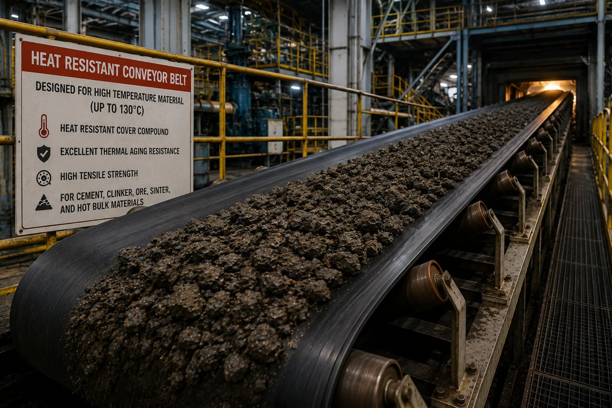
World Prime Services Heat-Resistant Conveyor Belt is engineered for continuous and intermittent conveying of hot bulk materials where conventional rubber covers may harden, crack, soften, blister or lose adhesion under thermal exposure.
The belt combines heat-resistant rubber compounds with a thermally stable adhesion system and a selected textile or steel-cord tension member. Typical conveyed materials include cement clinker, sintered ore, coke, foundry sand, hot ash, fertilizer products and other elevated-temperature bulk solids.
Selection must consider material temperature, peak temperature, particle size, contact duration, belt speed, loading profile, ambient conditions and cooling between loading cycles.
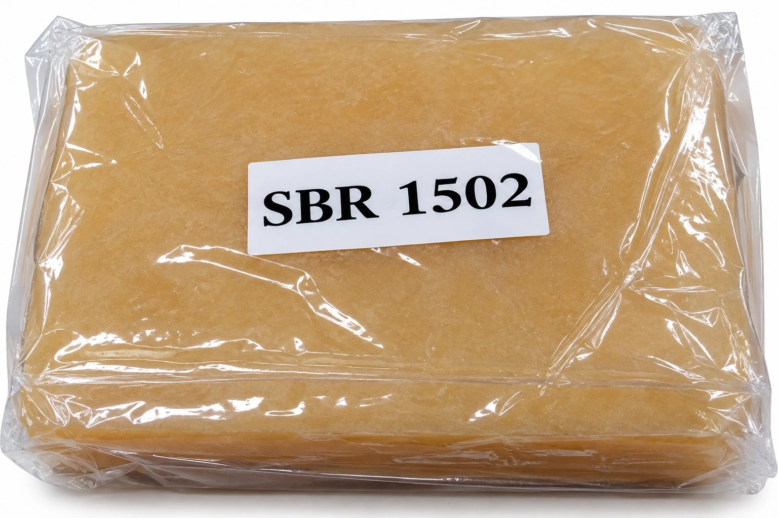
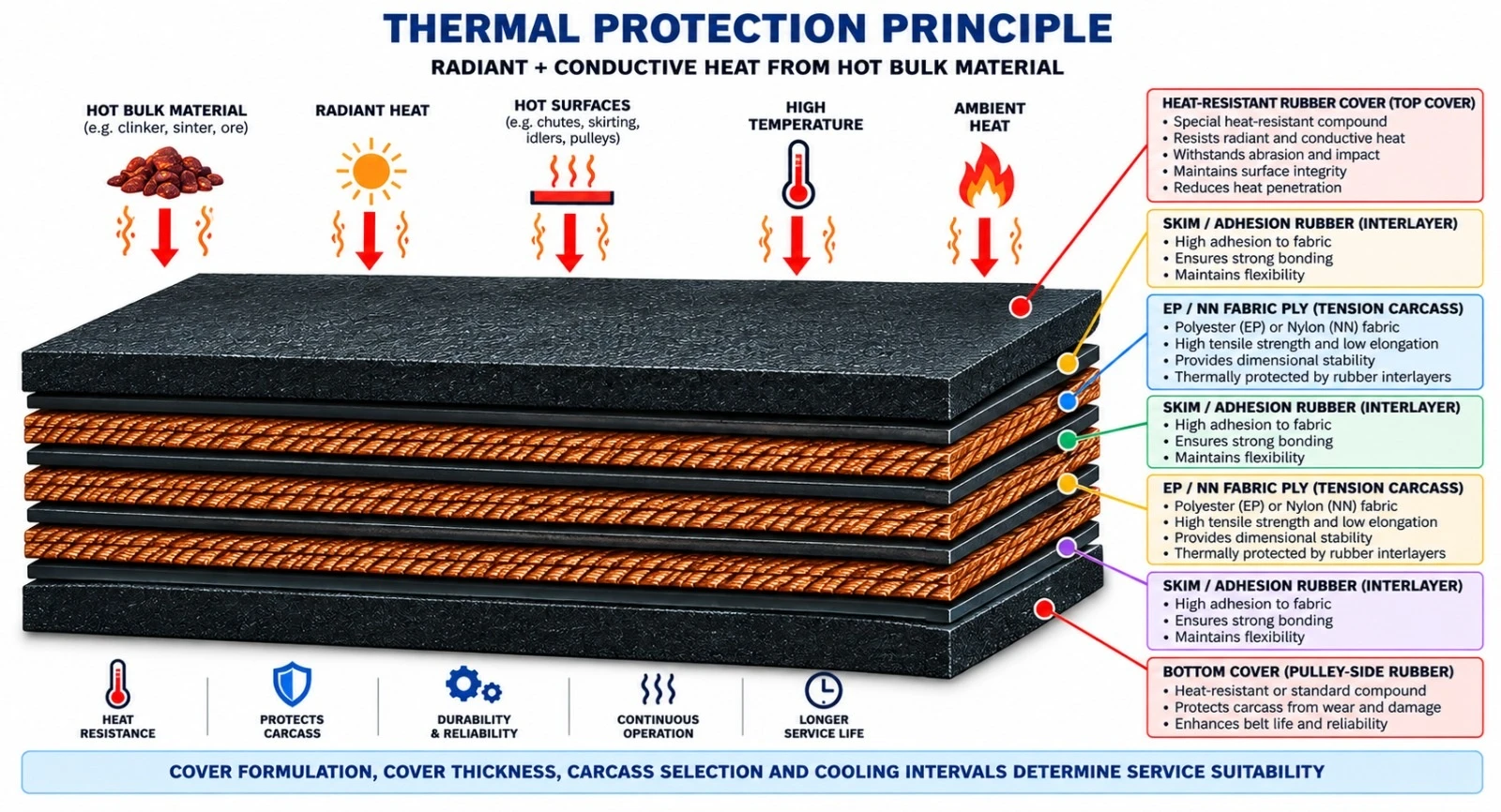
Heat reaches the belt through conduction from the conveyed material and through radiant heat from the process environment. The top cover is the first thermal barrier; its compound and thickness are therefore critical to carcass protection and belt life.
Heat-resistant belting should be selected from the real thermal duty rather than nominal material temperature alone. Large hot lumps, slow belt speed and continuous contact can create more severe cover temperatures than fine material conveyed at higher speed.
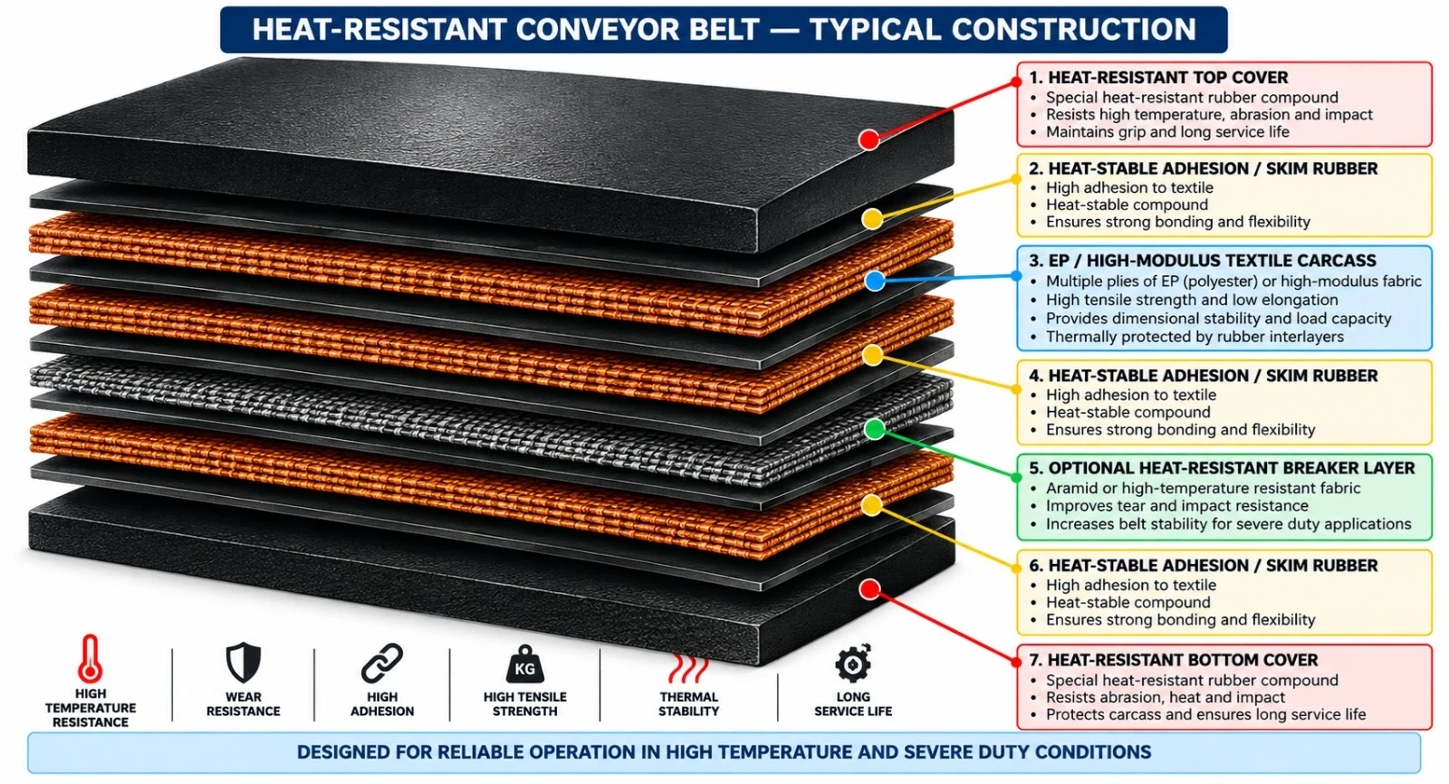
Typical construction uses a heat-resistant top cover, heat-stable skim rubber, a load-bearing carcass, optional breaker reinforcement and a heat-resistant bottom cover.
| Component | Engineering Function | Typical Option |
|---|---|---|
| Heat-resistant top cover | Primary thermal and wear barrier | Heat-resistant / high-temperature compound |
| Heat-stable skim rubber | Transfers load and protects adhesion under heat | Thermally stable bonding system |
| Load-bearing carcass | Carries operating tension | EP fabric / high-strength textile / steel cord |
| Optional breaker | Improves impact and tear resistance | Textile / transverse reinforcement |
| Bottom cover | Protects pulley-side carcass | Heat-resistant rubber |
HR-1 Series — Heat-resistant fabric belt for moderate elevated-temperature bulk handling.
HR-2 Series — Higher thermal-duty construction for clinker, coke, sinter and similar materials.
HR-3 Series — Severe thermal-duty belt using premium heat-resistant cover and adhesion compounds.
HT Series — Engineered high-temperature belt for severe or intermittent peak-temperature exposure.
HR-ST Series — Heat-resistant steel cord construction for long-distance, high-tension and heavy-load hot-material conveying.
HR-AR Series — Heat-resistant anti-rip construction with optional breaker or transverse reinforcement.
Heat-resistant cover compounds are formulated to retain useful mechanical properties after thermal ageing. Compound selection targets resistance to hardening, cracking, softening, swelling and premature loss of tensile strength or elongation.
Premium formulations may use heat-stable elastomer systems selected according to required temperature resistance and service conditions. Final compound chemistry is application-specific.
EP fabric is widely suited to heat-resistant conveyor belts because of its dimensional stability, low elongation and good load-carrying performance. High-strength textile constructions are available for heavier service, while steel cord carcasses may be used for high-tension long-distance systems.
| Carcass | Key Characteristic | Typical Duty |
|---|---|---|
| EP Fabric | Low elongation and good dimensional stability | General and heavy heat-resistant service |
| High-Strength EP | Higher tensile capacity | Longer or higher-load systems |
| NN Fabric | High flexibility and impact tolerance | Selected hot-material duties |
| Steel Cord | Very high strength and low elongation | Long-distance high-tension hot-material conveying |
Primary applications include cement plants, clinker handling, steel mills, sinter plants, coke plants, foundries, metallurgical facilities, fertilizer plants, power generation and other industrial processes handling hot bulk solids.
| Industry | Typical Hot Material | Engineering Focus |
|---|---|---|
| Cement | Clinker | Heat, abrasion and impact resistance |
| Steel / Sintering | Sintered ore | Severe thermal and mechanical duty |
| Coke Plants | Coke | Heat and abrasion resistance |
| Foundries | Foundry sand / cast process materials | Thermal cycling |
| Metallurgy | Hot minerals and process solids | High-temperature reliability |
| Power Generation | Hot ash and process residues | Heat and continuous-duty resistance |
Temperature ratings must be treated as project-specific engineering values. Continuous material temperature, intermittent peak temperature and actual belt-surface temperature are different parameters and should not be used interchangeably.
Where material exceeds the selected belt capability, engineering controls such as cooling, shorter contact time, reduced lump size, improved loading distribution or alternative belt technology should be evaluated.
| Duty Band | Indicative Service Concept | Selection Note |
|---|---|---|
| Moderate Heat | Elevated-temperature material | Confirm actual belt-surface temperature |
| High Heat | Hot clinker, coke or sinter duty | Use enhanced heat-resistant compound |
| Severe Heat | High continuous thermal load | Premium heat-stable construction required |
| Extreme / Peak Heat | Intermittent severe peaks | Project-specific engineering and validation required |
Cover thickness, carcass construction, pulley diameter, transition geometry, belt speed and take-up design must be coordinated. Thermal ageing can reduce cover flexibility and adhesion, making correct pulley sizing and maintenance especially important.
Hot-vulcanized splicing is generally preferred for critical heat-resistant belt service. Splice compounds must be thermally compatible with the parent belt. Cure parameters and splice geometry must follow the approved belt construction and project specification.
Conveyor alignment, pulley condition, loading-zone geometry and take-up setting should be verified before commissioning. Initial operation should include monitoring of tracking, belt-surface temperature, splice condition and localized hot spots.
Routine inspection should focus on cover hardening, cracking, blistering, delamination, carcass exposure, splice degradation and localized thermal damage. Infrared temperature monitoring can support identification of abnormal thermal zones.
| Inspection Point | Typical Symptom | Action |
|---|---|---|
| Top cover | Hardening / cracking | Review temperature and compound suitability |
| Cover surface | Blistering / softening | Check peak temperature and trapped heat |
| Carcass adhesion | Delamination | Repair or replace affected section |
| Splice | Cracking / separation | Immediate engineered inspection |
| Loading zone | Localized burn marks | Improve loading and cooling control |
| Pulley side | Heat damage / glazing | Inspect return-side heat exposure |
Quality control should include dimensional inspection, carcass verification, cover physical-property testing, adhesion testing, thermal-ageing evaluation and production traceability.
| Control Item | Purpose |
|---|---|
| Cover tensile strength | Verify compound mechanical performance |
| Elongation at break | Evaluate flexibility retention |
| Hardness after heat ageing | Evaluate thermal ageing behavior |
| Cover-to-ply adhesion | Verify structural integrity |
| Ply-to-ply adhesion | Verify carcass bonding |
| Dimensional inspection | Confirm width and thickness |
| Traceability | Identify production batch and construction |
ISO 4195:2012 specifies requirements and test methods for the relative heat resistance of rubber conveyor-belt covers, including permissible changes in hardness, elongation at break and tensile strength after heat exposure. It applies to belts with cover thickness of at least 4 mm. A third edition is under publication in 2026 and is intended to replace the 2012 edition.
| Parameter | Catalogue Option / Engineering Range | Remarks |
|---|---|---|
| Belt width | Approx. 400–3,200+ mm | Project-dependent |
| Carcass | EP / NN / high-strength textile / steel cord | Selected by tension and distance |
| Top cover | Typically 4–15+ mm | Thermal and wear duty dependent |
| Bottom cover | Typically 2–8+ mm | Project-dependent |
| Heat grade | HR / severe HR / high-temperature engineered | Final rating by application |
| Breaker reinforcement | Optional | Recommended for severe impact / lump duty |
| Edge construction | Cut edge / moulded edge | Construction-dependent |
| Splicing | Hot vulcanized preferred | Heat-compatible splice materials |
| Application Severity | Material Profile | Recommended Protection | Typical Construction |
|---|---|---|---|
| Moderate | Warm to hot bulk solids | Heat-resistant cover | EP fabric carcass |
| High | Clinker, coke, hot minerals | Enhanced heat-resistant compound | High-strength EP + thicker top cover |
| Very High | Sinter and severe continuous heat | Premium thermal protection | Engineered textile or steel cord |
| Extreme | Severe intermittent peak exposure | Project-specific high-temperature system | Engineered carcass + premium cover package |
| Project / Site | |
| Industry | |
| Conveyed Material | |
| Normal Material Temperature (°C) | |
| Maximum / Peak Material Temperature (°C) | |
| Estimated Belt Surface Temperature (°C) | |
| Continuous or Intermittent Exposure | |
| Maximum Lump Size | |
| Capacity (t/h) | |
| Bulk Density | |
| Belt Width (mm) | |
| Belt Speed (m/s) | |
| Center Distance (m) | |
| Inclination (°) | |
| Required Carcass Type | |
| Required Belt Strength | |
| Top Cover (mm) | |
| Bottom Cover (mm) | |
| Required Heat Grade | |
| Breaker / Anti-Rip Requirement | |
| Drive Pulley Diameter | |
| Tail Pulley Diameter | |
| Take-Up Type | |
| Splice Requirement | |
| Ambient Temperature | |
| Cooling Available? | |
| Applicable Standard / Customer Specification | |
| Additional Notes |
| Product Attribute | World Prime Services Heat-Resistant Conveyor Belt |
|---|---|
| Primary Function | Conveying hot bulk solids under elevated thermal exposure |
| Core Protection | Heat-resistant rubber covers and thermally stable adhesion system |
| Carcass Options | EP / NN / high-strength textile / steel cord |
| Key Industries | Cement, steel, sinter, coke, foundry, metallurgy and power |
| Optional Protection | Breaker, anti-rip and project-specific reinforcement |
| Engineering Basis | Temperature, contact time, particle size, belt speed, load and conveyor geometry |
Industrial Rubber and Fabric Flat Belt for Mechanical Power Transmission

World Prime Services Transmission Belt is a heavy-duty rubber and fabric flat belt engineered for friction-based mechanical power transmission between rotating pulleys. The belt transfers torque from a drive pulley to a driven pulley through controlled belt tension, wrap angle and friction at the pulley interface.
The construction uses high-strength textile reinforcement bonded to durable rubber compounds to provide flexibility, dimensional stability, fatigue resistance and reliable frictional grip. The product is suitable for industrial equipment such as fans, blowers, pumps, agricultural machinery, workshop machines, process drives and selected heavy-duty power transmission systems.
| Engineering Objective | Operational Benefit |
|---|---|
| High tensile strength | Supports mechanical power transmission under sustained belt tension |
| Controlled elongation | Improves speed stability and reduces retensioning frequency |
| High flex-fatigue resistance | Supports repeated flexing over the drive and driven pulleys |
| High-friction pulley surface | Improves torque transfer and reduces slippage |
| Strong inter-layer adhesion | Maintains construction integrity under cyclic tension |
| Custom width and thickness | Allows matching to pulley geometry and transmitted load |
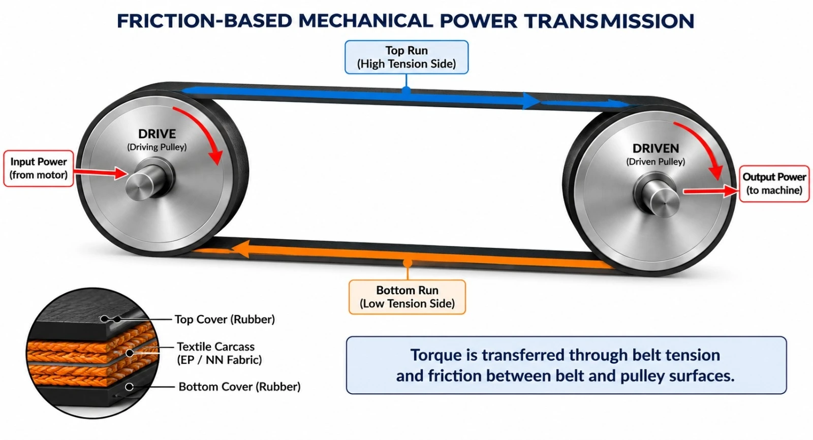
Flat transmission belts operate by friction between the belt and pulley surfaces. The difference between the tight-side tension and the slack-side tension produces the effective tangential force that transmits mechanical power. System capacity is influenced by belt speed, pulley diameter, wrap angle, coefficient of friction, pre-tension and allowable belt tension.
Correct pulley alignment and appropriate tension are essential. Excessive tension increases bearing loads and belt fatigue, while insufficient tension can cause slippage, heat generation, pulley surface polishing and unstable speed transmission.
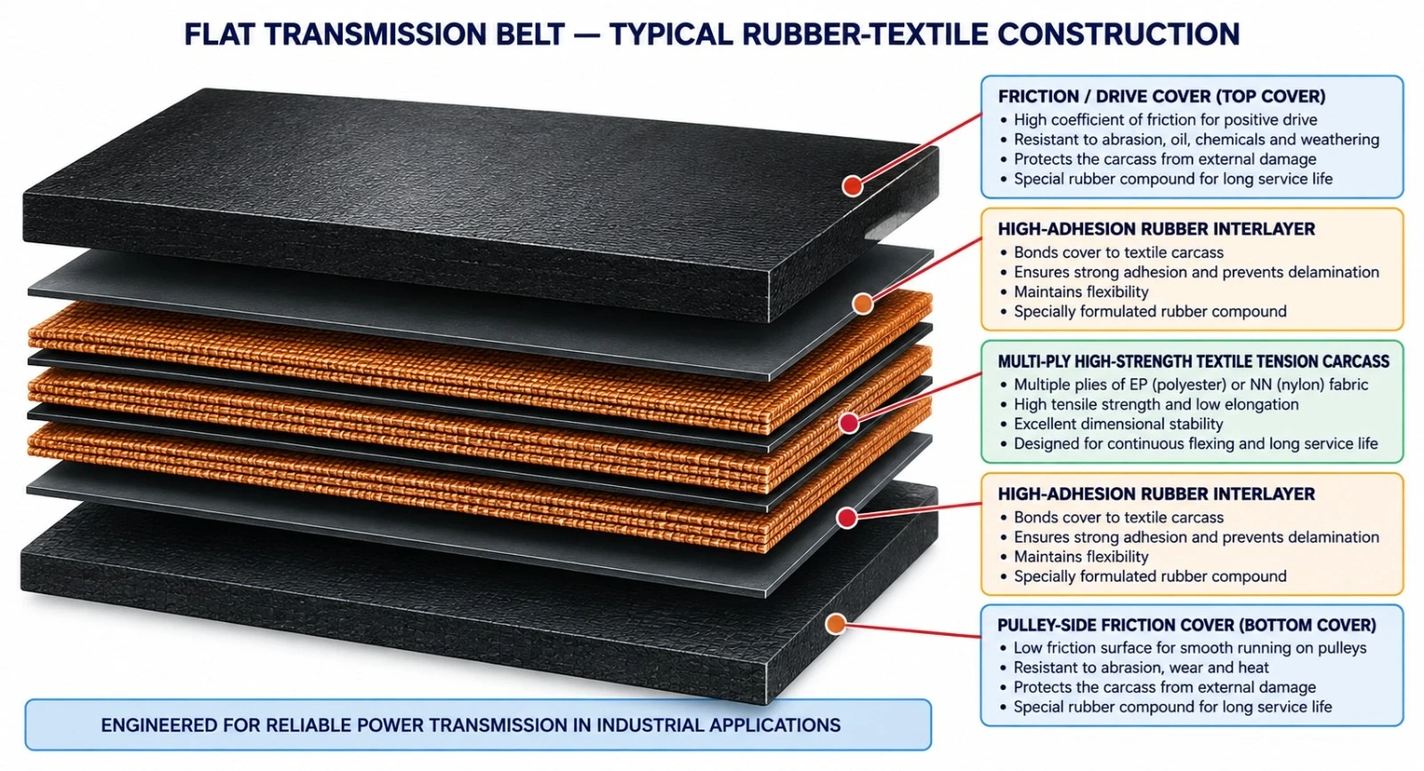
| Component | Engineering Function | Typical Options |
|---|---|---|
| Drive / friction cover | Provides frictional contact with the pulley | High-friction rubber, wear-resistant rubber, textile impression |
| Intermediate adhesion layer | Transfers cyclic tension between the cover and the carcass | High-adhesion rubber system |
| Tension carcass | Carries the operating tension and transmitted load | EP, NN or high-strength textile fabric |
| Pulley-side cover | Provides grip and protects the carcass | Rubber friction surface or fabric-backed option |
| Edges | Protects the belt layers | Cut edge or wrapped/moulded edge |
| Series | Description |
|---|---|
| TB-EP | EP Fabric Transmission Belt — low-elongation polyester/nylon textile construction for industrial drives requiring stable length and reliable tension retention. |
| TB-NN | Nylon Fabric Transmission Belt — flexible, fatigue-resistant construction for applications with frequent flexing and moderate shock loading. |
| TB-WR | Wrapped-Edge Transmission Belt — multi-ply textile construction with protected wrapped edges for improved edge durability and traditional flat-belt drive systems. |
| TB-CE | Cut-Edge Transmission Belt — precision-cut belt edges with rubber-sealed sides for dimensional control and standard industrial transmission systems. |
| TB-HD | High-Tension Heavy-Duty Transmission Belt — reinforced textile construction for crushers, heavy blowers, process machinery and large industrial drives. |
| TB-SP | Special-Compound Transmission Belt — dedicated engineered covers for oil, heat, antistatic, weathering or other special operating environments. |
| Carcass Type | Key Characteristics | Best Fit | Engineering Note |
|---|---|---|---|
| EP Fabric | Low elongation, strong dimensional stability | Industrial drives and longer center distances | Preferred for stable running length |
| NN Fabric | High flexibility and fatigue resistance | Frequent flexing and smaller pulley systems | Higher elongation than EP |
| High-Strength Fabric | High tensile density | Heavy-duty transmission systems | Project-specific construction |
| Multi-Ply Reinforced Fabric | Load distribution across multiple plies | Traditional flat-belt drives | Thickness and pulley diameter must be matched |
| Surface Type | Primary Function | Typical Use |
|---|---|---|
| Smooth Rubber Friction Surface | Balanced grip and wear resistance | General industrial pulleys |
| High-Friction Rubber | Improved traction and reduced slippage | High torque or variable load |
| Textile-Impression Surface | Controlled friction and stable pulley contact | Traditional flat-belt applications |
| Rubber/Fabric Combination | Flexibility with controlled pulley interface | Special machine drives |
| Wear-Resistant Cover | Improved life in dusty environments | Cement, mining support, processing plants |
The values below represent a catalog engineering envelope. Final belt width, thickness, carcass strength and cover construction are confirmed per the pulley geometry, required power and operating speed.
| Parameter | Catalogue Option / Range | Remarks |
|---|---|---|
| Belt width | Approx. 20–1,500+ mm | Project-specific industrial widths |
| Total thickness | Approx. 3–20+ mm | Depends on ply count and cover system |
| Carcass | EP / NN / high-strength textile | Selected by tension and flexing service |
| Ply construction | Multi-ply textile | Project-specific |
| Edge type | Cut edge / wrapped edge | Per application |
| Surface | Smooth rubber / high-friction / textile impression | Selected by pulley interface |
| Operating temperature | Compound-dependent | Heat-resistant grades available |
| Special properties | Oil-resistant / antistatic / heat / weathering | Project-specific |
| Design Factor | Engineering Effect |
|---|---|
| Pulley Diameter | Controls belt flexing stress and carcass fatigue |
| Belt speed | Affects transmitted power, centrifugal forces and heat generation |
| Center Distance | Influences belt length, vibration and take-up requirement |
| Wrap angle | Controls available frictional traction |
| Pulley crown | Supports flat-belt tracking, where applicable |
| Pulley surface condition | Affects the coefficient of friction and slippage |
| Shaft alignment | Critical for tracking and edge life |
Power transmitted by a flat-belt system depends on the effective tension difference and belt speed. Final belt design must be selected from the actual drive power, pulley diameters, rotational speed, center distance, service factor and starting load.
| Input Data | Why It Is Required |
|---|---|
| Motor/drive power (kW) | Determines the required transmitted power |
| Drive pulley RPM | Defines belt speed together with pulley diameter |
| Drive pulley diameter | Influences flexing stress and belt speed |
| Driven pulley diameter | Defines the speed ratio |
| Center Distance | Controls belt length and dynamic behavior |
| Starting torque | Determines peak belt tension |
| Operating hours / duty cycle | Influences fatigue life |
| Environment | Determines the special-compound requirement |
| Industry / Equipment | Typical Drive | Primary Belt Requirement |
|---|---|---|
| Fans & Blowers | Motor-to-fan drive | High flexibility and stable friction |
| Pumps | Industrial pump drive | Continuous, reliable torque transfer |
| Agricultural Machinery | Threshers, processors and auxiliary drives | Durability and flexible operation |
| Workshop Machines | Lathes, presses and machine tools | Smooth running and stable tracking |
| Process Plants | Mechanical auxiliary equipment | Continuous service and wear resistance |
| Cement & Mining Support Equipment | Fans, crushers and auxiliary machinery | Heavy-duty tensile strength |
| General Manufacturing | Production machine drives | Low maintenance and dimensional stability |
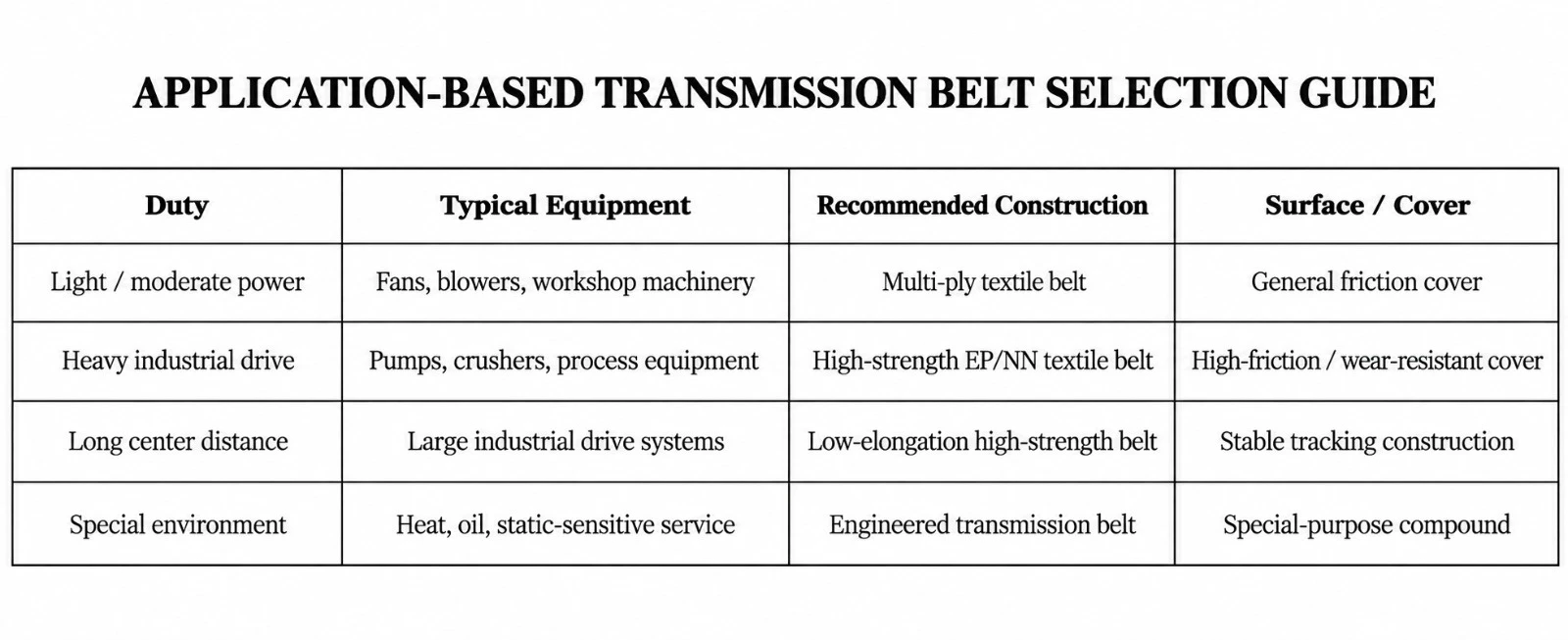
| Inspection Point | What to Check | Recommended Action |
|---|---|---|
| Belt surface | Glazing, cracking, wear or contamination | Clean or replace as needed |
| Edges | Fraying or edge contact | Correct alignment |
| Pulleys | Wear, contamination or damaged crown | Repair / clean |
| Tension | Slippage or excessive bearing load | Adjust to the approved level |
| Carcass | Layer separation or exposed fabric | Replace the belt |
| Drive vibration | Misalignment or unstable tension | Inspect the entire drive geometry |
| Control Item | Purpose | Typical Stage |
|---|---|---|
| Width and thickness | Confirm dimensional compliance | Final inspection |
| Carcass identification | Verify textile construction | Production |
| Tensile strength | Confirm load capacity | Laboratory |
| Elongation | Assess dimensional stability | Laboratory |
| Inter-layer adhesion | Verify structural integrity | Laboratory |
| Surface / friction consistency | Confirm pulley-contact behavior | Production / final |
| Visual inspection / traceability | Detect defects and identify the batch | Final inspection / dispatch |
| Special Grade | Primary Duty | Typical Application |
|---|---|---|
| TB-HR | Heat-resistant | Hot process areas and elevated ambient temperature |
| TB-OR | Oil-resistant | Oil-contaminated industrial environments |
| TB-AS | Antistatic | Static-sensitive machinery and dry process plants |
| TB-WR | Weather-resistant | Outdoor drive systems |
| TB-AR | Abrasion-resistant | Dusty and abrasive industrial environments |
Transmission belt designs may reference international pulley and belt standards, where applicable. Since many legacy flat-belt dimensional standards have been withdrawn, final design dimensions must be agreed directly between buyer and supplier and validated against the actual drive system.
| Reference | Relevance |
|---|---|
| ISO/TC 41 / SC 1 | International standards committee for friction belt drives |
| ISO 14890:2026 | Reference for rubber/plastics-covered textile conveyor belts, where conveyor-type textile construction is used |
| Project-specific drive calculation | Required for pulley diameter, speed, tension, power and service factor |
| Customer / machinery OEM specification | Final dimensional and operating requirements |
The current ISO catalog shows several historical flat transmission-belt dimensional standards, including ISO 22, ISO 63, ISO 99 and ISO 100, as withdrawn. This catalog therefore treats dimensions as project-specific engineering data, rather than presenting obsolete ISO dimensional limits as current requirements.
| Project / Site | |
| Industry | |
| Driven Equipment | |
| Motor/Drive Power (kW) | |
| Starting Torque / Service Factor | |
| Drive Pulley Diameter (mm) | |
| Driven Pulley Diameter (mm) | |
| Drive Pulley Speed (rpm) | |
| Required Driven Speed (rpm) | |
| Center Distance (mm) | |
| Pulley Face Width (mm) | |
| Required Belt Width (mm) | |
| Preferred Belt Thickness (mm) | |
| Required Carcass Type | |
| Required Edge Type | |
| Surface / Friction Requirement | |
| Operating Temperature | |
| Oil Exposure | |
| Antistatic Requirement | |
| Outdoor Exposure / Weathering | |
| Operating Hours per Day | |
| Applicable OEM / Customer Standard | |
| Additional Operating Notes |
Industrial Multi-Ply Rubberized Canvas Belting for Mechanical Power Transmission

World Prime Services Flat Rubber-Canvas Transmission Belt is a traditional multi-ply flat power-transmission belt designed to transfer mechanical power between rotating pulleys through controlled friction and belt tension.
The construction combines multiple layers of rubberized canvas with friction covers and high-adhesion bonding rubber. This architecture provides a balance of tensile strength, flexibility, fatigue resistance, dimensional stability and pulley grip for industrial power-transmission systems.
Typical uses include fans, blowers, pumps, machine tools, agricultural machinery, process equipment, workshops and other mechanical drive systems where a flat friction belt is preferred.
| Engineering Objective | Operational Benefit |
|---|---|
| High longitudinal tensile strength | Supports sustained mechanical power transmission |
| Multi-ply canvas reinforcement | Distributes load through several tension-carrying layers |
| Controlled elongation | Improves speed stability and reduces frequent re-tensioning |
| High-friction rubber surfaces | Improves grip on drive and driven pulleys |
| High inter-ply adhesion | Supports resistance to delamination under cyclic flexing |
| Flexible flat-belt geometry | Suitable for long center distances and traditional industrial drives |
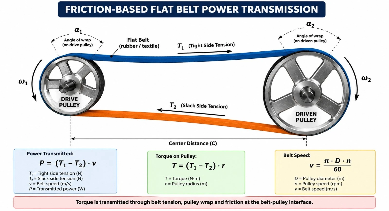
Flat transmission belts transfer torque by friction between the belt and pulley surfaces. The difference between tight-side and slack-side tension creates the effective tangential force that transmits power from the drive pulley to the driven pulley.
Transmission capacity depends on belt speed, pulley diameter, wrap angle, coefficient of friction, pre-tension, center distance and allowable working stress. Excessive tension increases shaft and bearing loads, while insufficient tension can cause slip, heat generation and unstable speed transmission.
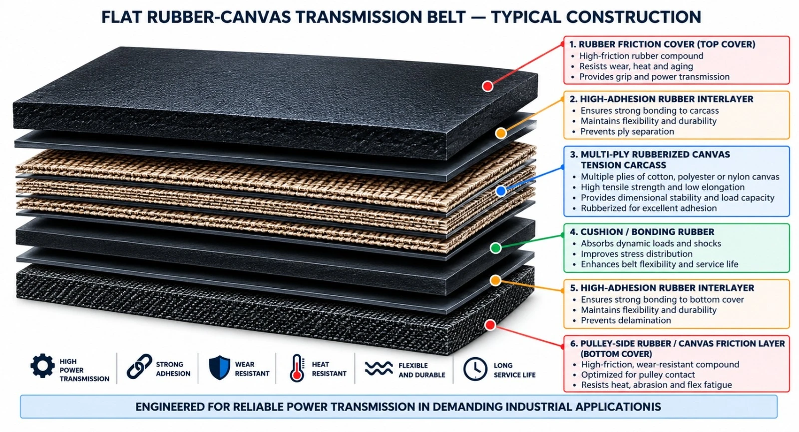
| Component | Engineering Function | Typical Options |
|---|---|---|
| Rubber friction cover | Provides frictional contact and wear protection | Smooth rubber / high-friction rubber |
| High-adhesion interlayer | Bonds cover and carcass | Rubber bonding compound |
| Rubberized canvas tension carcass | Carries tensile load | Cotton canvas / synthetic canvas / blended high-strength fabric |
| Cushion rubber | Distributes stress between carcass layers | Application-specific formulation |
| Pulley-side friction layer | Provides grip and protects lower plies | Rubber or rubberized canvas surface |
| Edge construction | Protects carcass plies | Cut edge / wrapped edge |
RC-TB Standard Series — General-Purpose Rubber-Canvas Transmission Belt. Multi-ply rubberized canvas construction for conventional workshop, agricultural and industrial machinery drives.
RC-TB EP Series — Synthetic-Reinforced Rubber-Canvas Belt. Enhanced low-elongation textile construction for more stable running length and higher mechanical duty.
RC-TB Wrapped Edge Series — Traditional flat transmission belt with protected wrapped edges for improved resistance to edge wear.
RC-TB Cut Edge Series — Precisely cut and sealed belt edges for dimensional control and standard industrial pulley systems.
RC-TB Heavy-Duty Series — High-strength multi-ply construction for large fans, blowers, crushers, pumps and process machinery.
RC-TB Special Compound Series — Engineered rubber-canvas belts for oil, heat, antistatic, weather or other special operating conditions.
The load-bearing section of the belt consists of multiple canvas plies impregnated and bonded with rubber. Each ply contributes tensile capacity while the rubber matrix transfers stress between layers and permits repeated flexing around pulleys.
| Carcass | Main Characteristics | Typical Use | Engineering Note |
|---|---|---|---|
| Cotton Canvas | Traditional friction-belt construction with good grip and flexibility | Legacy and moderate-duty machinery | Higher elongation than modern synthetic fabrics |
| Synthetic Canvas | Improved tensile strength and dimensional stability | Modern industrial flat-belt drives | Better stability at higher loads |
| EP Reinforced Canvas | Low elongation and strong dimensional stability | Longer center distances and heavy duty | Preferred for stable running length |
| NN Reinforced Canvas | High flexibility and fatigue resistance | Frequent flexing and shock duty | Higher elongation than EP |
| Surface Type | Primary Function | Typical Use |
|---|---|---|
| Smooth Rubber Friction Surface | Balanced grip and wear resistance | General industrial pulleys |
| High-Friction Rubber | Improved traction and reduced slip | Higher torque transmission |
| Rubberized Canvas Surface | Traditional controlled-friction interface | Conventional flat-belt drives |
| Wrapped Canvas Surface | Improved edge and surface durability | Traditional heavy-duty applications |
| Wear-Resistant Rubber | Extended life in dusty environments | Cement, mining support equipment and process plants |
The following values represent a general engineering envelope. Final dimensions and construction must be selected from actual pulley geometry, transmitted power and operating conditions.
| Parameter | Catalogue Option / Range | Remarks |
|---|---|---|
| Belt width | Approx. 20–1,500+ mm | Project-specific industrial widths |
| Total thickness | Approx. 3–25+ mm | Depends on ply count and cover construction |
| Number of plies | Multi-ply canvas construction | Selected from load and flexibility requirements |
| Carcass | Cotton / synthetic / EP / NN reinforced canvas | Project-specific |
| Edge type | Cut edge / wrapped edge | Application-dependent |
| Surface | Smooth rubber / high-friction / canvas impression | Selected by pulley interface |
| Operating temperature | Compound-dependent | Heat-resistant grades available |
| Special properties | Oil / heat / antistatic / weather resistance | Project-specific |
Current ISO 22:1991 specifies principal dimensions and tolerances for flat transmission belts and corresponding pulleys. The standard remains current and was confirmed in 2025.
| Control Item | Purpose |
|---|---|
| Belt width | Ensures compatibility with pulley face width |
| Belt length | Controls fit and center adjustment |
| Total thickness | Influences flexibility and minimum pulley diameter |
| Width tolerance | Supports tracking and pulley fit |
| Length tolerance | Supports correct take-up and center-distance adjustment |
| Edge quality | Reduces tracking disturbance and premature edge wear |
Flat belts require correct pulley geometry for stable running. Depending on the drive layout, a crowned pulley may be used to assist tracking. Pulley surface condition, finish and balance directly influence belt life, slip and vibration.
| Design Factor | Engineering Impact |
|---|---|
| Pulley diameter | Controls carcass bending fatigue |
| Pulley face width | Must provide adequate support across belt width |
| Pulley crown | Can assist flat-belt tracking |
| Pulley finish | Influences friction and belt wear |
| Pulley balance | Important at higher rotational speeds |
| Shaft alignment | Critical to tracking and edge life |
The final belt must be selected from actual transmitted power, speed and service factor rather than width alone. High speed increases centrifugal effects and may reduce effective pulley pressure, while low speed requires greater effective tension for the same transmitted power.
| Required Input | Why It Matters |
|---|---|
| Motor power (kW) | Defines required transmitted power |
| Drive pulley diameter | Defines belt velocity and bending stress |
| Drive pulley rpm | Determines belt speed |
| Driven pulley diameter | Defines speed ratio |
| Starting torque | Determines peak tension demand |
| Service factor | Accounts for shock, duty cycle and operating severity |
| Operating hours | Influences fatigue-life requirement |
Center distance influences belt length, wrap angle, vibration characteristics and available adjustment. ISO 155:2019 provides limiting values for adjustment of centers for belt drives, while ISO 22:1991 covers principal flat-belt and pulley dimensions.
| Design Element | Engineering Requirement |
|---|---|
| Center Distance (m) | Must suit pulley diameters and belt geometry |
| Adjustment range | Must allow installation and re-tensioning |
| Take-up method | Manual screw, sliding motor base or engineered tensioning system |
| Initial pre-tension | Sufficient to prevent slip at design load |
| Run-in allowance | Permits controlled re-tensioning after initial operation |
| Industry / Equipment | Typical Drive | Primary Belt Requirement |
|---|---|---|
| Fans & Blowers | Motor-to-fan drive | Stable friction and flexible operation |
| Pumps | Industrial pump drive | Reliable continuous torque transfer |
| Agricultural Machinery | Threshers, mills and processors | Durability and shock tolerance |
| Workshop Machinery | Lathes, presses and line shafts | Smooth running and tracking stability |
| Process Plants | Auxiliary rotating equipment | Continuous duty and dimensional stability |
| Cement & Mining Support Equipment | Fans, crushers and ancillary machinery | Heavy-duty tensile capacity |
| General Manufacturing | Production machinery drives | Low maintenance and reliable power transfer |
| Inspection Point | What to Check | Recommended Action |
|---|---|---|
| Belt surface | Glazing, cracking, wear or contamination | Clean or replace as required |
| Edges | Fraying or edge contact | Correct alignment |
| Pulleys | Wear, contamination or damaged crown | Repair / clean |
| Tension | Slip or excessive bearing load | Adjust to approved level |
| Carcass | Ply separation or exposed canvas | Replace belt |
| Drive vibration | Misalignment or unstable tension | Inspect full drive geometry |
| Control Item | Purpose | Typical Stage |
|---|---|---|
| Width and thickness | Dimensional compliance | Final inspection |
| Ply count / carcass verification | Confirm construction | Production |
| Tensile strength | Verify load-carrying capability | Laboratory |
| Elongation | Assess dimensional stability | Laboratory |
| Ply adhesion | Verify structural integrity | Laboratory |
| Surface consistency | Confirm friction interface | Production / final |
| Visual inspection and traceability | Detect defects and identify manufacturing batch | Final / dispatch |
| Special Grade | Primary Duty | Typical Application |
|---|---|---|
| RC-HR | Heat-resistant | Hot process areas |
| RC-OR | Oil-resistant | Oil-contaminated environments |
| RC-AS | Antistatic | Static-sensitive machinery |
| RC-WR | Weather-resistant | Outdoor transmission systems |
| RC-AR | Abrasion-resistant | Dusty and abrasive environments |
| Reference | Relevance |
|---|---|
| ISO 22:1991 | Flat transmission belts and corresponding pulleys — dimensions and tolerances |
| ISO 155:2019 | Belt drives — pulleys — limiting values for adjustment of centers |
| ISO 254:2011 | Belt drives — pulleys — quality, finish and balance |
| ISO/TC 41/SC 1 | International standards committee responsible for friction belt drives |
| Customer / Machinery OEM Specification | Final drive-specific dimensions and operating requirements |
ISO 22:1991 remains current and was confirmed in 2025. Earlier standalone standards for flat-belt widths, lengths, pulley diameters and pulley crowns were withdrawn and consolidated into ISO 22:1991.
| Project / Site | |
| Industry | |
| Driven Equipment | |
| Motor/Drive Power (kW) | |
| Starting Torque / Service Factor | |
| Drive Pulley Diameter (mm) | |
| Driven Pulley Diameter (mm) | |
| Drive Pulley Speed (rpm) | |
| Required Driven Speed (rpm) | |
| Center Distance (mm) | |
| Available Center Adjustment (mm) | |
| Pulley Face Width (mm) | |
| Required Belt Width (mm) | |
| Preferred Belt Thickness (mm) | |
| Required Carcass Type | |
| Required Number of Plies | |
| Required Edge Type | |
| Surface / Friction Requirement | |
| Operating Temperature | |
| Oil Exposure | |
| Antistatic Requirement | |
| Outdoor Exposure / Weathering | |
| Operating Hours per Day | |
| Applicable OEM / Customer Standard | |
| Additional Operating Notes |
Integrally Moulded Profile Belts for Inclined Conveying with Material Return Control

This revised catalogue specification replaces operating-installation illustrations with frontal or near-frontal product photographs of the actual rubber belt surface and moulded profile. The objective is to allow direct visual comparison of each pattern geometry.
| Requirement | Catalogue Standard |
|---|---|
| Image type | Real product photograph wherever a technically matching source image is available |
| View | Frontal / top-facing view of the belt carrying surface |
| Background | Neutral factory, warehouse or plain background preferred |
| Excluded views | No conveyor-in-operation photographs in the pattern model pages |
| Branding | Third-party logos and watermarks are not presented as World Prime Services branding |
| Purpose | Clear comparison of rib geometry, profile arrangement and open/closed pattern design |
| Pattern Model | Technical Description |
|---|---|
| Open V Chevron | Open V-shaped moulded ribs; suitable for free-flowing and selected wet materials. |
| Closed V Chevron | Continuous V geometry for stronger material retention. |
| 16 mm Low Chevron | Lower profile for smaller lump sizes and moderate incline applications. |
| 32 mm High Chevron | Higher profile for larger lump sizes and demanding inclined conveying. |
| Herringbone / Fishbone | Alternating fishbone-type grip profile for bulk or selected packaged goods. |
| Multiprof / Multi-Chevron | Multiple low-profile gripping sections for packages and selected bulk materials. |
| U-Top / U Profile | U-shaped moulded cleat configuration for material containment. |
| Y-Top / Y Profile | Y-shaped cleat geometry for directional retention. |
| C-Top / C Profile | C-shaped moulded profile for free-flowing material elevation. |
| V-Top | V-shaped cleat configuration for inclined conveying. |
| Mini-Bucket Profile | Pocket-forming moulded pattern for aggressive elevation of free-flowing material. |
| B-Top | Special moulded top profile for application-specific elevation. |
| F-18 / F-36 | Specialized moulded profile family for free-flowing material handling. |
| Chevron 24 / 42 | Chevron profile family for aggressive inclined transfer. |
| Wave Grip | Wave-form grip profile retained as a World Prime Services catalogue option. |
| Truck Tyre Model — Staggered Chevron | Alternating diagonal tread-style ribs based on the supplied physical product reference. |
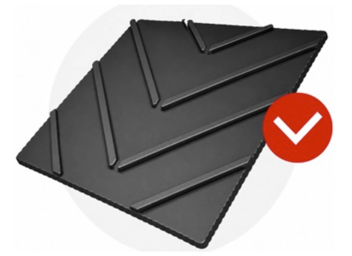




| Pattern Model | Profile Geometry | Typical Materials / Loads | Primary Engineering Function |
|---|---|---|---|
| Open V Chevron | Open V-shaped center cleats | Wet fines, sand, gravel, aggregate | Open drainage and rollback control |
| Closed V Chevron | Continuous V-shaped cleats | Dry granules, ore, aggregate | Higher material retention |
| 16 mm Low Chevron | 16 mm integral chevron | Small to medium lumps | Moderate incline and compact pulley design |
| 32 mm High Chevron | 32 mm integral chevron | Coarse bulk and larger lumps | Aggressive retention for demanding incline service |
| Herringbone / Fishbone | Directional herringbone grip | Packaged goods and selected bulk | High-grip surface |
| Rufftop Type | Textured high-friction surface | Boxes, bags, baggage | Non-slip conveying of packaged goods |
| Multiprof / Multi-Chevron | Multi-purpose low profile | Agriculture, oily material, wood chips, wet sand, packaged goods | Drainage, quiet running and cleanability |
| U-Top / U Profile | U-shaped moulded cleats | Free-flowing bulk | Pocket-forming retention |
| Y-Top / Y Profile | Y-shaped cleats | Granules and selected bulk | Directional retention |
| C-Top / C Profile | Curved C profile | Free-flowing materials | Repeated retention zones |
| V-Top | Repeated V-shaped cleats | Inclined bulk | General-purpose grip |
| Mini-Bucket Profile | Moulded bucket-type pockets | Fine / free-flowing materials | Aggressive lifting |
| B-Top | Special elevated profile | Application-specific bulk | Enhanced surface grip |
| F-18 / F-36 | Directional moulded cleats | Selected free-flowing materials | Profile-specific grip |
| Chevron 24 / 42 | Heavy-duty chevron family | Aggregate and coarse bulk | Higher-capacity incline service |
| Wave Grip | Wave-shaped profile | Wet / slip-prone material | Continuous grip |
| Truck Tyre Model | Staggered diagonal tread-type cleats | Aggregate, gravel, crushed stone, recycling | Open staggered grip and rollback control |
Chevron and profiled belts are selected primarily when conveyor incline is too steep for a conventional smooth belt. Integrally moulded profiles help prevent material rollback. Profile selection must consider material type, moisture, lump size, belt speed, incline angle, loading conditions and return-side support.
Industry references include low- and high-profile chevron constructions, plus specialized moulded profiles U-Top, Y-Top, Mini-Bucket, Chevron, C-Top, V-Top, F-series and B-Top. Low-profile families such as Multiprof and herringbone are also used for packaged goods and selected bulk materials.
| Profile Family | Indicative / Published Industry Reference | Typical Selection Basis |
|---|---|---|
| Very Low / Low Profile | Approximately 5 mm or less on some low-profile designs | Packaged goods, bags, agricultural products, wood chips, wet sand |
| Low Chevron | 16 mm reference profile | Smaller lumps and moderate inclines |
| High Chevron | 32 mm reference profile | Larger lumps and steeper/demanding applications |
| Special Recycling Chevron | Examples of 16, 20, 30, 40 or 50 mm | Recycling systems and special return-side arrangements |
| Custom Moulded Profile | Project-specific | Material and conveyor geometry |
| Application | Recommended Pattern Families |
|---|---|
| Aggregate / Gravel | Open V, High Chevron, Truck Tyre Model, 24/42 Chevron |
| Coal / Ore | Closed V, High Chevron, Herringbone |
| Sand / Wet Sand | Open V, Herringbone, Truck Tyre Model |
| Recycling | High Chevron, Herringbone, Truck Tyre Model, special recycling profiles |
| Packaged Goods / Bags / Bales | Multiprof, Multi-Chevron, low-profile patterns |
| Agricultural Bulk | Open V, U, Y, Herringbone / Multiprof |
| Free-Flowing Materials | U-Top, Y-Top, Mini-Bucket, C-Top, V-Top and specialized cleat profiles |
The final commercial Word catalogue should use one dedicated model section per pattern, with a large frontal/top-facing real product photograph followed by the model name, profile geometry, typical profile height, suitable material, recommended inclination concept, carcass options, cover grades and ordering parameters. Images must visually match the stated pattern; generic operating photographs should not be substituted for product-detail photographs.
The photo gallery is included for technical visual comparison of the pattern geometries. Final rib height, pitch, pattern width, edge recess and carcass construction must follow the approved product drawing and purchase specification.
World Prime Services Patterned (Chevron) Conveyor Belts are engineered for inclined conveying, where a conventional smooth rubber belt can allow material rollback or unstable load retention. The catalog line combines integrally moulded profile geometries with textile carcass constructions selected according to operating tension, material characteristics, conveyor gradient, belt speed and duty.
Pattern selection is application-specific. Open profiles favor drainage and release; closed, tall profiles increase retention; low-profile, high-grip surfaces suit packaged goods and selected bulk materials; specialized cleat geometries create pockets or directional restraint.


| Profile Class | Typical Reference Height | Typical Duty | Engineering Note |
|---|---|---|---|
| Very Low Grip Surface | Low profile | Packaged goods and non-slip service | Selected by surface-friction requirement |
| Low Chevron | 16 mm | Smaller lumps and moderate to steep incline | Industry-consolidated low-chevron class |
| Medium Profile | Approx. 17–25 mm | General bulk | Material-dependent |
| High Chevron | 32 mm | Larger lumps and demanding incline | Industry-consolidated high-chevron class |
| Custom / Severe Service | Project-specific | Special recycling, coarse bulk or unusual geometry | Manufacturing drawing required |
Incline capacity is not determined by profile height alone. Material friction, moisture, lump size, loading stability, belt speed and profile pitch must all be considered. Industry-published ranges for profiled belts include applications around 30° for multi-purpose low-profile designs and up to approximately 40–45° for suitable chevron systems, subject to full conveyor engineering.
| Carcass Option | Characteristics | Typical Application |
|---|---|---|
| EP Fabric | Polyester warp / nylon weft; low elongation, high tensile strength and moisture resistance | General-purpose and heavy-duty patterned belts |
| NN Fabric | Nylon reinforcement with flexibility and impact absorption | Shorter conveyors and impact-oriented service |
| High-Strength Multi-Ply EP | Higher tensile rating with dimensional stability | Longer or higher-load inclined conveyors |
| Engineered Reinforcement | Project-specific construction | Special profile, width or operating tension |
| Cover Type | Primary Property | Typical Duty |
|---|---|---|
| Abrasion-Resistant | Wear resistance for mineral bulk | Mining, quarry, aggregate |
| Oil-Resistant | Resistance to mineral/vegetable oil exposure | Recycling and oily bulk |
| Heat-Resistant | Resistance to elevated material temperature | Hot bulk handling |
| Cold-Resistant | Low ambient-temperature flexibility | Cold climate and storage |
| Antistatic | Controlled electrical resistance | Static-sensitive environments |
| Flame-Retardant | Reduced flame propagation | Specified fire-risk applications |
| Ozone / UV Resistant | Resistance to environmental cracking | Outdoor conveyor service |
| Parameter | Catalog Range/Option | Selection Basis |
|---|---|---|
| Belt Width (mm) | Approx. 400–1,600 mm in standard patterned ranges; wider project-specific options possible | Conveyor and profile tooling |
| Pattern Height | Low profile up to 32+ mm; project-specific custom profiles | Material and incline |
| Carcass | EP / NN / engineered reinforcement | Operating tension |
| Cover Grade | AR / OR / HR / CR / AS / FR and project-specific | Environment and material |
| Pattern Width | Project-specific, with edge margin | Skirt seal arrangement |
| Pattern Pitch | Project-specific | Lump size and return-side support |
| Splicing | Hot-vulcanized, factory endless or approved mechanical | Construction and duty |
| Edge | Moulded edge or engineered edge | Manufacturing specification |
| Application | Preferred Pattern Families | Key Selection Driver |
|---|---|---|
| Mining / Quarry | Open V, Closed V, High Chevron, Truck Tyre Model | Lump size, abrasion and incline |
| Sand / Gravel | Open V, Herringbone, Truck Tyre Model | Drainage and rollback |
| Agriculture | Multiprof, Open V, U, Y | Gentle handling and drainage |
| Packaged Goods / Bags / Baggage | Herringbone, Rufftop Type, Multiprof | Surface grip |
| Recycling | High Chevron, Herringbone, Truck Tyre Model | Irregular material and incline |
| Wood Chips / Biomass | Multiprof, Chevron, U Profile | Bulk retention |
| Oily Materials | Multiprof with oil-resistant cover | Oil exposure and grip |
| Wet Bulk | Open V, Multiprof, Wave Grip | Drainage and non-slip performance |
| Item | Requirement |
|---|---|
| Pattern Orientation | Install per the approved conveying direction and pattern drawing |
| Loading | Center the load and minimize uncontrolled impact |
| Skirt Seals | Maintain adequate smooth edge margin around the raised profiles |
| Return Idlers | Use a support arrangement compatible with the profile |
| Pulley Diameter | Select according to carcass, splice and profile flexibility |
| Cleaning | Use scrapers designed for profiled conveying surfaces |
| Tracking | Correct structural alignment before increasing belt tension |
| Inspection | Monitor cracking, tearing, separation and abnormal profile wear |
| Splicing | Hot vulcanization preferred for critical heavy-load service |
| Quality Control Item | Verification |
|---|---|
| Pattern Geometry | Profile type, height, pitch and orientation |
| Dimensions | Belt width, overall thickness and edge margin |
| Carcass | Construction and tensile rating |
| Cover | Compound grade and physical properties |
| Profile Integrity | Moulding quality and profile-to-cover adhesion |
| Adhesion | Bonding between cover and layers |
| Traceability | Production batch and inspection record |
Ordering data should include: conveyed material, bulk density, moisture, maximum lump size, required capacity, conveyor incline, belt speed, center distance, belt width, carcass rating, top and bottom cover thickness, preferred pattern, profile height, pattern pitch, edge margin, pulley diameters, return idler arrangement, splicing method and required cover grade.
All dimensions, incline capacities and profile selections in this catalog are engineering guidance. Final belt construction must be confirmed based on the actual conveyor system and an approved manufacturing specification. Trade model names used in this catalog identify World Prime Services product configurations; third-party company names are intentionally excluded from the product presentation.
High-Angle Conveyor Belt with Corrugated Sidewalls and Cleats
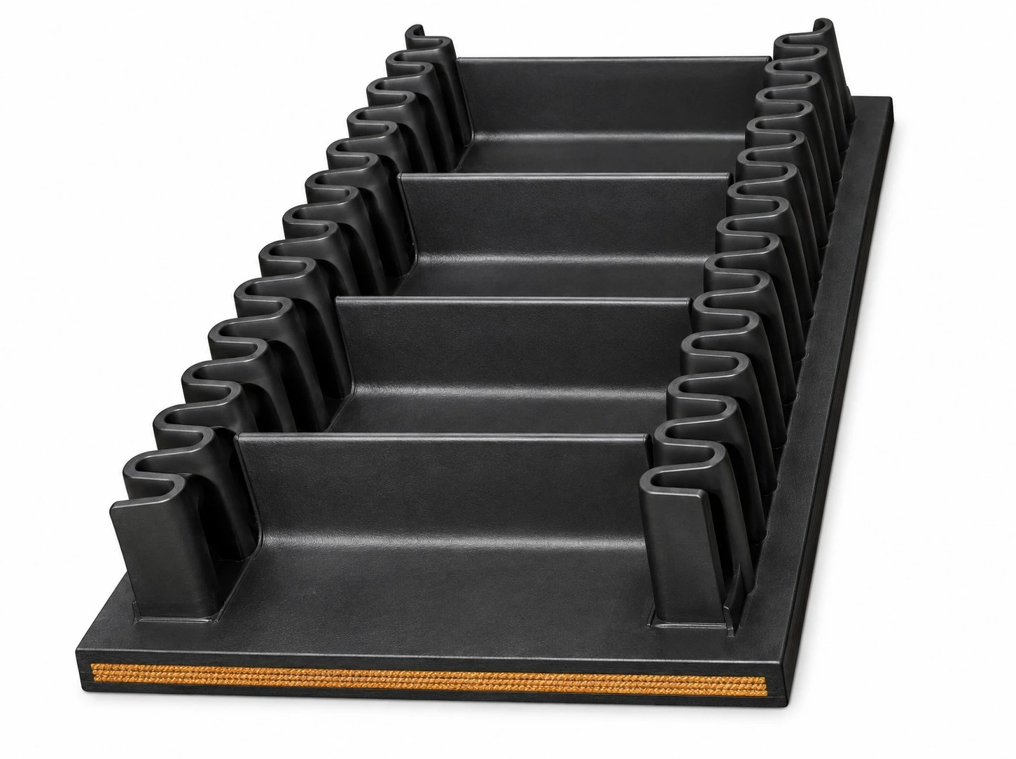
World Prime Services Sidewall Conveyor Belt is engineered for continuous conveying of bulk materials on horizontal, inclined, steep-angle and vertical routes. The system integrates a transversely rigid base belt, flexible corrugated sidewalls and application-selected transverse cleats to create stable material pockets, maximize lift within restricted plant space and reduce intermediate transfer points.

| Symbol | Definition |
|---|---|
| Bw | Overall base belt width. |
| Sh | Corrugated sidewall height. |
| Sw | Sidewall foot width. |
| Cp | Cleat pitch, measured center to center. |
| Ch | Cleat height. |
| Cw | Effective cleat width between the sidewalls. |
| Fs | Free edge zone between the sidewall foot and the belt edge. |


Sidewall selection is governed by the required pocket volume, belt width, loading severity, pulley geometry and repeated-flexing service. The product line is organized into N, S and ES service classes, with special profiles available for engineered applications.
| Type | Duty | Typical Height Range | Application |
|---|---|---|---|
| N | Light Service | 40–120 mm | Compact systems and moderate material loading. |
| S | Medium Service | 120–300 mm | General industrial steep-angle conveying. |
| ES | Heavy / Extra-Strong Service | 300–630 mm | High-capacity, high-lift and severe-service conveying. |
| Sidewall Type | Typical Heights (mm) |
|---|---|
| N | 40, 60, 80, 100, 120 |
| S | 120, 160, 200, 240, 300 |
| ES | 300, 400, 500, 630 |
| Special | S136, S220, S270, S360 and project-specific profiles. |
Cleats support the material column and define the conveying pocket. Profile selection is matched to conveyor incline, material flow behavior, lump size, abrasion, impact and required discharge characteristics.
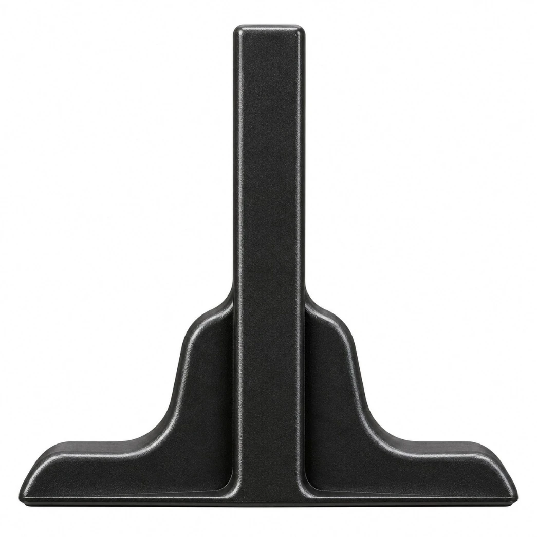
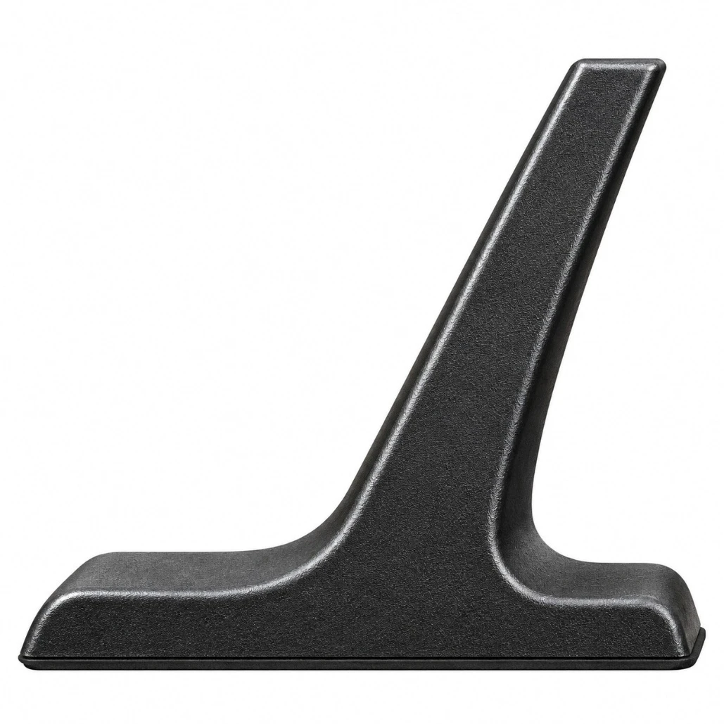
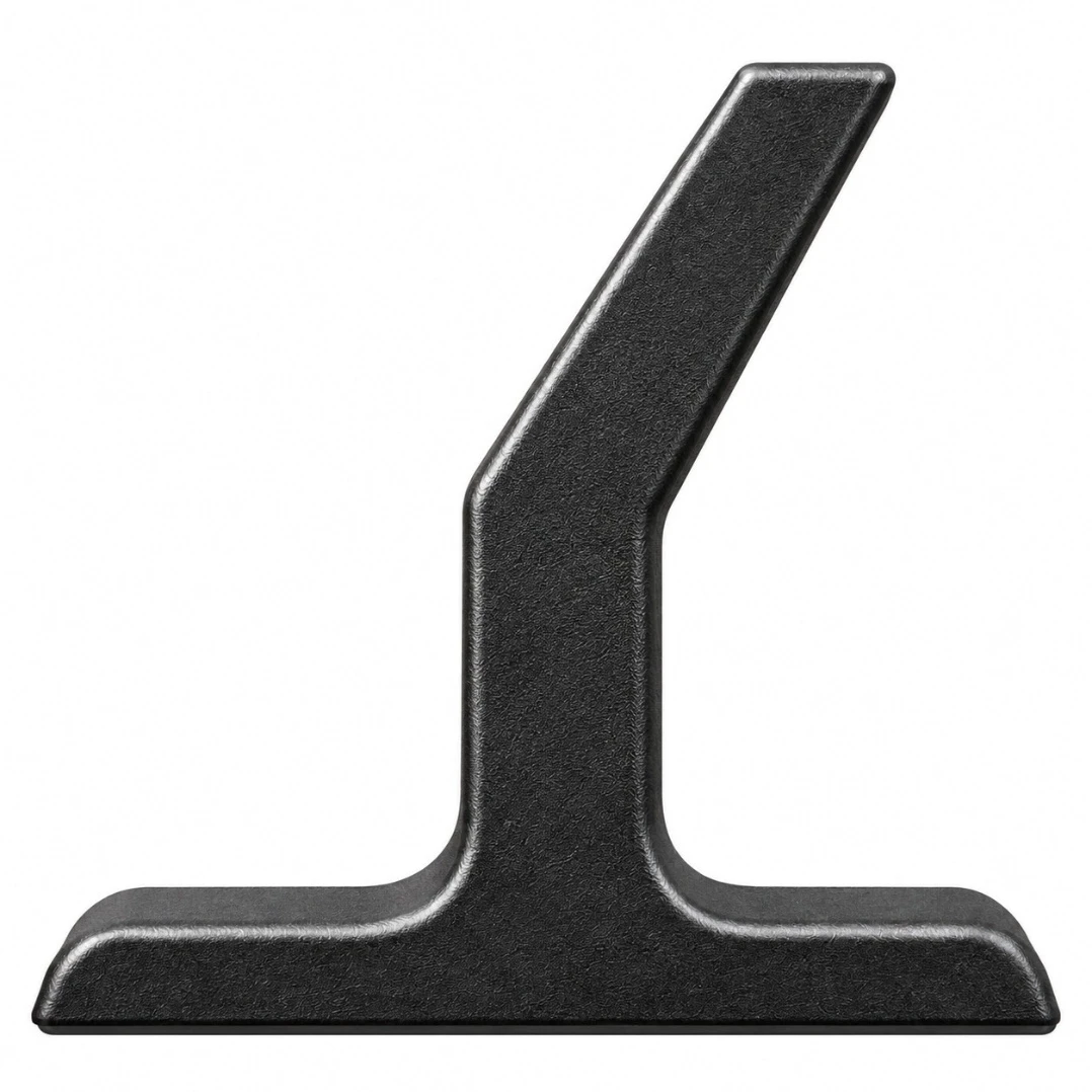
| Type | Duty | Typical Use |
|---|---|---|
| T | General Service | Moderate-angle conveying and free-flowing bulk materials. |
| TS | Reinforced T | Higher abrasion and mechanical loading. |
| C | Retention Profile | Controlled pocket formation and reduced rollback. |
| TC | High Retention | Steep-angle and vertical conveying. |
| TCS | Reinforced High Retention | Severe abrasive, high-angle, high-load service. |
| Type | Typical Heights (mm) |
|---|---|
| T | 35, 55, 75, 90, 110, 140, 180, 220, 280, 360, 460, 580 |
| TS | 110, 140, 180, 220, 280, 360, 460, 580 |
| C | 55, 75, 90, 110, 140 |
| TC | 35, 55, 75, 90, 110, 140, 180, 220, 280 |
| TCS | 180, 220, 280, 360, 460, 580 |
| Incline | Typical Cleat Family | Engineering Consideration |
|---|---|---|
| 0°–20° | T / C | Containment and controlled feeding. |
| 20°–40° | T / TS / C | Selection according to bulk density, lump size and flowability. |
| 40°–60° | TC / TCS | High-retention pocket geometry generally preferred. |
| 60°–90° | TC / TCS | Deep pocket system requiring coordinated sidewall height and cleat pitch. |
For horizontal and low-angle service, where edge containment is required without transverse material support, the belt can be supplied with corrugated sidewalls only. This arrangement preserves edge containment while maintaining an open conveying surface.

| Construction | Typical Duty | Characteristics |
|---|---|---|
| EP Textile | General industrial / heavy-duty service | Low elongation and good dimensional stability. |
| NN Textile | Impact and flexing service | High flexibility and fatigue resistance. |
| CC Textile | Moderate service | General-purpose textile construction. |
| Transversely Rigid Textile | High-angle sidewall service | Improved transverse stiffness and pocket support. |
| Steel Cord / Steel-Reinforced | High lift / high tension | Long centers and severe high-tension applications. |
| Compound | Typical Service |
|---|---|
| Abrasion-resistant | Ore, aggregate, clinker, coal and abrasive solids. |
| Heat-resistant | Elevated-temperature bulk materials. |
| Oil-resistant | Oily or hydrocarbon-contaminated materials. |
| Flame-Resistant | Applications requiring specified flame behavior. |
| Cold resistance | Low-temperature environments. |
| Acid / Alkali Resistant | Compatible fertilizer and chemical services. |

The following table presents reference dimensional combinations between base belt width (Bw), sidewall height (Sh) and cleat height (Ch), with the resulting typical effective conveying width.
| Bw (mm) | Sh (mm) | Ch (mm) | Typical Effective Conveying Width |
|---|---|---|---|
| 300 | 40 / 60 / 80 | 35 / 55 / 75 | 120–180 mm |
| 400 | 60 / 80 / 100 | 55 / 75 / 90 | Approx. 180 mm |
| 500 | 80 / 100 / 120 | 75 / 90 / 110 | Approx. 250 mm |
| 650 | 100 / 120 / 160 | 90 / 110 / 140 | 300–350 mm |
| 800 | 120 / 160 / 200 | 110 / 140 / 180 | 410–460 mm |
| 1000 | 160 / 200 / 240 | 140 / 180 / 220 | Approx. 550 mm |
| 1200 | 160 / 200 / 240 / 300 | 140 / 180 / 220 / 280 | 630–690 mm |
| 1400 | 200 / 240 / 300 / 400 | 180 / 220 / 280 / 360 | 770–830 mm |
| 1600 | 200 / 240 / 300 / 400 | 180 / 220 / 280 / 360 | 910–970 mm |
| 1800 | 240 / 300 / 400 / 500 | 220 / 280 / 360 / 460 | 1010–1110 mm |
Detailed dimensional reference between belt width, sidewall height (H), cleat height (Ch), sidewall foot width (Sw), effective cleat width (Cw) and free edge zone (Fs), for the typical sidewall and cleat combinations listed above. The exact values of Sw, Cw and Fs for each combination must be confirmed against the approved technical product drawing, as they vary with the selected sidewall class and cleat profile.
| Parameter | Required Information |
|---|---|
| Material | Name, bulk density, moisture, abrasiveness and temperature. |
| Capacity (t/h) | Normal and peak t/h and/or m³/h. |
| Particle Size | Maximum lump size and size distribution. |
| Geometry | Horizontal run, vertical lift, incline and transitions. |
| Belt | Width, speed, tensile rating and length. |
| Sidewall | Type N / S / ES and required Sh. |
| Cleat | Type T / TS / C / TC / TCS, Ch and Cp. |
| Mechanical | Pulley diameters, drive arrangement and take-up. |
| Environment | Temperature, oil, flame, chemicals and outdoor exposure. |
| Splice | Open, endless, hot-vulcanized or on-site splice requirement. |
| Industry | Typical Materials |
|---|---|
| Mining & Minerals | Iron ore, copper ore, coal, concentrate and crushed rock. |
| Cement & Aggregates | Limestone, clinker, gypsum, sand and gravel. |
| Steel & Metallurgy | Coke, sinter, pellets, fluxes and process materials. |
| Ports & Terminals | Compact high-angle loading and transfer systems. |
| Power Generation | Coal, biomass and selected fuel materials. |
| Fertilizers & Chemicals | Granules, salts and compatible bulk solids. |
| Recycling | Shredded products, glass and industrial waste. |
The dimensions and combinations presented are typical engineering references. Final belt construction, sidewall profile, cleat profile, rubber compound, pulley diameter and operating limits must be confirmed through application-specific engineering review before manufacturing.
| Bw (mm) | H (mm) | Ch (mm) | Sw (mm) | Cw (mm) | Fs (mm) |
|---|---|---|---|---|---|
| 300 | 40 | 35 | 35 | 180 | 35 |
| 300 | 60 | 55 | 50 | 120 | 40 |
| 300 | 80 | 75 | 50 | 120 | 40 |
| 400 | 60 | 55 | 50 | 180 | 60 |
| 400 | 80 | 75 | 50 | 180 | 60 |
| 400 | 100 | 90 | 50 | 180 | 60 |
| 500 | 80 | 75 | 50 | 250 | 75 |
| 500 | 100 | 90 | 50 | 250 | 75 |
| 500 | 120 | 110 | 50 | 250 | 75 |
| 650 | 100 | 90 | 50 | 250 | 100 |
| 650 | 120 | 110 | 50 | 250 | 100 |
| 650 | 160 | 140 | 75 | 300 | 100 |
| 800 | 120 | 110 | 50 | 460 | 120 |
| 800 | 160 | 140 | 75 | 410 | 120 |
| 800 | 200 | 180 | 75 | 410 | 120 |
| 1000 | 160 | 140 | 75 | 550 | 150 |
| 1000 | 200 | 180 | 75 | 550 | 150 |
| 1000 | 240 | 220 | 75 | 550 | 150 |
| 1200 | 160 | 140 | 75 | 690 | 180 |
| 1200 | 200 | 180 | 75 | 690 | 180 |
| 1200 | 240 | 220 | 75 | 690 | 180 |
| 1200 | 300 | 280 | 105 | 630 | 180 |
| 1400 | 200 | 180 | 75 | 830 | 210 |
| 1400 | 240 | 220 | 75 | 830 | 210 |
| 1400 | 300 | 280 | 105 | 770 | 210 |
| 1400 | 400 | 360 | 105 | 770 | 210 |
| 1600 | 200 | 180 | 75 | 970 | 240 |
| 1600 | 240 | 220 | 75 | 970 | 240 |
| 1600 | 300 | 280 | 105 | 910 | 240 |
| 1600 | 400 | 360 | 105 | 910 | 240 |
| 1800 | 240 | 220 | 75 | 1110 | 270 |
| 1800 | 300 | 280 | 105 | 1050 | 270 |
| 1800 | 400 | 360 | 105 | 1050 | 270 |
| 1800 | 500 | 460 | 125 | 1010 | 270 |

Professional Product Catalog | Heavy-Duty Bulk Material Handling

Engineered for high-capacity conveying systems requiring exceptional belt width, dimensional stability, tensile performance and reliable service under demanding industrial operating conditions.
World Prime Services High-Strength Super-Wide Rubber Conveyor Belts are specified for large-capacity bulk handling installations, where conventional belt widths are insufficient. The product platform combines high-strength textile reinforcement, engineered rubber compounds and controlled wide-format vulcanization, to provide stable tracking, flex resistance, low operating elongation and reliable load support.
Typical applications include mining, ports and terminals, stockyard systems, metallurgy, power generation, aggregate handling, fertilizers, chemical processing and other high-throughput conveying services. Belt construction, width, tensile rating, cover grade and cover thickness are selected according to conveyor geometry, material characteristics and the operating environment.
| Component | Technical Description |
|---|---|
| Top cover | Engineered rubber compound selected for the conveyed material, abrasion severity and environmental exposure. |
| Carcass | High-strength multi-ply EP textile reinforcement; alternative reinforcement systems can be engineered for specific service. |
| Skim / Adhesion Rubber | High-adhesion rubber between the reinforcement plies, to promote carcass integrity and fatigue resistance. |
| Bottom cover | Rubber compound engineered for pulley contact, flexing performance and the service environment. |
| Edges | Moulded or cut edge construction, subject to belt design and manufacturing specification. |
| Parameter | Typical / Available Range | Engineering Note |
|---|---|---|
| Belt Width (mm) | 1.800–5.500 mm | Super-wide category; final manufacturable width subject to construction and project specification. |
| Overall Belt Thickness | 12–42 mm | Selected according to carcass, cover gauges and service. |
| Number of Fabric Plies | Typically 2–6 plies | Higher-service constructions subject to engineering review. |
| Top cover thickness | Typically 2–12 mm | Customized for wear, impact and service-life requirements. |
| Bottom cover thickness | Typically 1.5–6 mm | Customized according to pulley-side service. |
| Belt Length | Project-specific | Manufacturing and transport lengths subject to belt size and logistics. |
| Fabric Type | Approx. Thickness per Ply (mm) | 2 Camadas (N/mm) | 3 Camadas | 4 Camadas | 5 Camadas | 6 Camadas |
|---|---|---|---|---|---|---|
| EP100 | 0,85 | 200 | 300 | 400 | 500 | 600 |
| EP125 | 0,90 | 250 | 375 | 500 | 625 | 750 |
| EP150 | 0,90 | 300 | 450 | 600 | 750 | 900 |
| EP200 | 1,10 | 400 | 600 | 800 | 1.000 | 1.200 |
| EP250 | 1,25 | 500 | 750 | 1.000 | 1.250 | 1.500 |
| EP300 | 1,45 | 600 | 900 | 1.200 | 1.500 | 1.800 |
| EP350 | 1,65 | 700 | 1.050 | 1.400 | 1.750 | 2.100 |
| EP400 | 1,75 | 800 | 1.200 | 1.600 | 2.000 | 2.400 |
| EP500 | 2,55 | 1.000 | 1.500 | 2.000 | 2.500 | 3.000 |
| Service Type | Recommended Application |
|---|---|
| General / Abrasion-Resistant | Bulk materials under normal to severe abrasive service. |
| Heat-resistant | Hot conveyed materials; compound and temperature class selected by continuous and peak material temperature. |
| High-Temperature Resistant | Specialized elevated-temperature service, requiring improved thermal aging resistance. |
| Oil-resistant | Materials containing mineral or vegetable oils and greases, subject to compatibility review. |
| Acid & Alkali Resistant | Chemical handling where controlled resistance to specified acidic or alkaline exposure is required. |
| Cold resistance | Low-temperature environments requiring improved flexibility and cold-crack resistance. |
| Flame-Resistant | Applications requiring flame-performance characteristics per the specified project standard. |
| Characteristics | Design Objective |
|---|---|
| Longitudinal Strength | High load-carrying capacity for heavy-duty, long conveyor installations. |
| Operating Elongation | Controlled elongation for improved take-up management and dimensional stability. |
| Transverse Rigidity | Stable belt profile across very large widths, maintaining the required troughing. |
| Adhesion | Strong inter-ply and cover-to-carcass adhesion, for fatigue and separation resistance. |
| Flex Life | Engineered for repeated flexing cycles when pulley diameters are correctly selected. |
| Tracking Stability | Uniform construction and dimensional control to support stable operation on correctly aligned systems. |
| Impact / Wear Resistance | Cover and carcass combinations selected according to lump size, drop height and loading conditions. |
Mining and mineral processing • Coal handling • Iron ore and bulk terminals • Ports and ship-loading systems • Metallurgical plants • Power plants • Aggregate and quarry operations • Fertilizer plants • Chemical industry • Large stockyards • High-capacity overland and plant conveyors.
For correct belt selection, the following project data should be reviewed: required belt width; center distance; rise or fall; conveyor profile; belt speed; design capacity; bulk density; maximum lump size; material temperature; ambient temperature; moisture; oil or chemical exposure; loading impact; idler configuration; trough angle; pulley diameters; drive arrangement; take-up system; calculated operating tension; starting and braking conditions; splicing method; applicable safety and fire requirements.
| Inspection Item | Typical Control |
|---|---|
| Overall Width | Verified against the agreed manufacturing tolerance. |
| Overall Thickness | Measured at representative locations on the belt. |
| Cover Thickness | Top and bottom cover gauges verified against specification. |
| Tensile strength | Verified according to the specified carcass rating and applicable test method. |
| Elongation | Assessed according to the applicable standard / agreed specification. |
| Adhesion Strength | Cover-to-ply and inter-ply adhesion assessed where applicable. |
| Abrasion Resistance | Tested where required by the selected cover grade. |
| Visual Surface Quality | Inspection of uniformity, surface condition and manufacturing defects. |
| Dimensional Stability | Controlled for wide-format belt geometry and consistent construction. |
Product design and testing may be specified according to internationally recognized conveyor belt standards, such as ISO, DIN, EN, AS, RMA/ARPM, GB or other customer/project standards, depending on belt construction and destination market. The exact standard, cover grade and acceptance criteria must be stated in the purchase specification.
HIGH-STRENGTH SUPER-WIDE – [CARCASS TYPE/RATING] – [PLY COUNT] – [BELT WIDTH] – [TOP + BOTTOM COVER] – [COVER GRADE] – [STANDARD]
Example: HIGH-STRENGTH SUPER-WIDE – EP400 – 5 PLIES – 3200 mm – 8+4 mm – ABRASION RESISTANT – PROJECT STANDARD
All dimensions and performance values in this catalog are product platform reference data and must be confirmed for each order. Very wide belts require careful conveyor structural alignment, idler geometry, loading-zone design, transition length, pulley sizing and tension analysis. The final belt construction must be specifically engineered for the actual conveyor service. Special widths, constructions and compounds are available, subject to technical evaluation and manufacturing feasibility.
| Attribute | Value |
|---|---|
| Product | World Prime Services High-Strength Super-Wide Rubber Conveyor Belt |
| Primary Construction | High-strength EP textile carcass with engineered rubber covers |
| Width Class | Super-wide, project-specific |
| Duty | High-capacity, heavy-duty bulk material conveying |
| Customization | Width, tensile rating, plies, cover thickness and rubber compound |
The following visual reference illustrates representative super-wide heavy-duty rubber conveyor belt configurations, including installed conveying systems, wide-format belt production rolls and multi-ply EP carcass construction. Images are illustrative product representations for technical catalogue use.
| Visual Configuration | Product Indication | Typical Application |
|---|---|---|
| Installed Super-Wide Belt | High-width rubber conveyor belt operating on heavy-duty idler sets. | Mining, terminals, stockyards and high-capacity bulk handling. |
| Wide Belt Roll | Large-width finished conveyor belt supplied in project-specific production and shipping lengths. | New conveyor installation, replacement and expansion projects. |
| EP Multi-Ply Construction | Rubber covers with high-strength polyester/nylon fabric reinforcement and adhesion skim layers. | Heavy-duty conveying requiring strength, flexibility and dimensional stability. |
HIGH & SUPER WIDE BELT
Engineered for maximum strength, high load capacity and superior durability. Designed for high-volume bulk material handling in mining, ports, steel, cement and heavy industry.

| Property | Test Method | Unit | Standard Value |
|---|---|---|---|
| Tensile Strength (Warp/Weft) | ISO 252 | N/mm | ≥ 24 |
| Elongation at Break (Warp/Weft) | ISO 252 | % | ≤ 4.0 |
| Adhesion between Plies | ISO 252 | N/mm | ≥ 4.5 |
| Cover Rubber Thickness | ISO 252 | mm | 6 – 10 |
| Abrasion Resistance | ISO 4649 | mm³ | ≤ 200 |
| Ozone Resistance | ISO 1431-1 | - | No cracks |
| Heat Aging (70°C x 168h) | ISO 188 | - | Tensile change ≤ ±25% Elongation change ≤ ±25% |
| Belt Width (mm) | Ply Rating (EP) | Cover Thickness (mm) | Belt Length (m) | |
|---|---|---|---|---|
| Top | Bottom | |||
| 1800 – 2400 | EP 315 – EP 800 | 6 – 10 | 3 – 6 | 100 – 400 |
| 2400 – 3200 | EP 400 – EP 1000 | 6 – 10 | 3 – 6 | 100 – 400 |
| 3200 – 4200 | EP 500 – EP 1250 | 6 – 10 | 3 – 6 | 100 – 400 |
| 4200 – 5500 | EP 630 – EP 1600 | 6 – 10 | 3 – 6 | 100 – 400 |
| Ply Rating (EP) | Tensile Strength (N/mm) | |
|---|---|---|
| Warp | Weft | |
| EP 315 | ≥ 31.5 | ≥ 31.5 |
| EP 400 | ≥ 40.0 | ≥ 40.0 |
| EP 500 | ≥ 50.0 | ≥ 50.0 |
| EP 630 | ≥ 63.0 | ≥ 63.0 |
| EP 800 | ≥ 80.0 | ≥ 80.0 |
| EP 1000 | ≥ 100.0 | ≥ 100.0 |
| EP 1250 | ≥ 125.0 | ≥ 125.0 |
| EP 1600 | ≥ 160.0 | ≥ 160.0 |
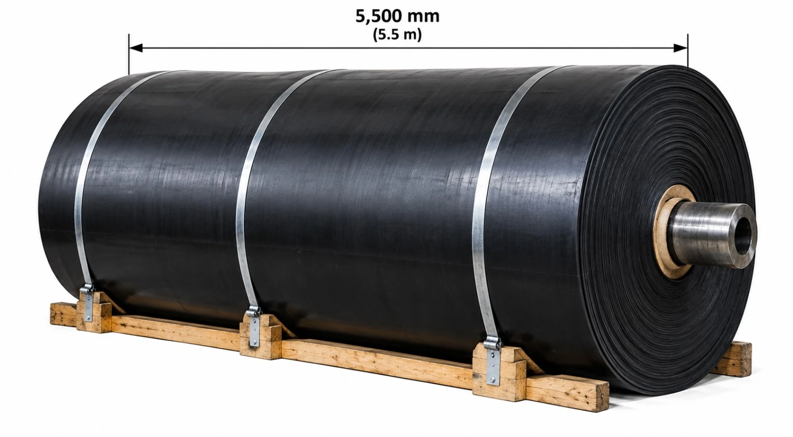
High Tension • Low Elongation • Long Distance • Heavy-Duty Bulk Material Conveying

World Prime Services Steel Cord Conveyor Belts are engineered for demanding bulk material handling systems requiring high longitudinal tensile strength, low operating elongation, high dynamic splice performance and long service life. The tension carcass consists of longitudinal high-strength steel cords embedded in specially formulated adhesion rubber and protected by application-specific top and bottom rubber covers.
Typical applications include mining, iron ore, copper, coal, aggregates, cement, steel mills, power generation, ports, terminals, overland conveyors, high-lift conveyors and other high-capacity continuous conveying installations.

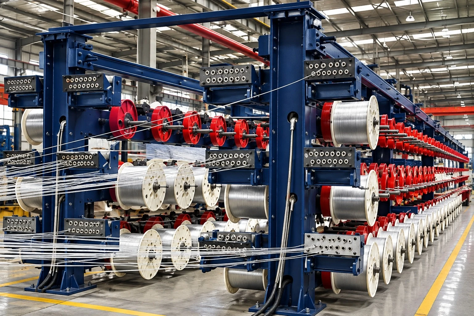

| Component | Technical Function |
|---|---|
| Carrying Side / Top Cover | Protects the tension carcass against abrasion, cutting, gouging, impact, heat and environmental exposure. |
| Core / Adhesion Rubber | Encapsulates the steel cords and provides high dynamic cord-to-rubber adhesion, plus corrosion protection. |
| Steel Cord Carcass | Longitudinal high-tensile steel cords, providing the primary load-carrying strength. |
| Transverse Reinforcement | Optional special textile, fabric or steel reinforcement, engineered to improve puncture, impact and longitudinal tear-propagation resistance. |
| Edge Rubber | Protects the belt edges and internal carcass against mechanical and environmental damage. |
| Pulley Side / Bottom Cover | Protects the carcass on the return side and provides proper pulley contact and flexing performance. |
The special construction incorporates transverse reinforcement positioned between the rubber cover and the longitudinal steel cord carcass. The reinforcement is oriented approximately perpendicular to the main longitudinal steel cords and is engineered to improve puncture resistance, impact loading and longitudinal tear propagation.
Depending on the required level of protection, the special transverse textile reinforcement can be installed on the carrying side only or on both the carrying and pulley sides. Severe-service constructions may alternatively employ transverse steel cords or a steel breaker reinforcement.

| Symbol | Description |
|---|---|
| B | Overall belt width |
| bt | Effective / used belt width |
| d | Steel cord diameter |
| bk | Belt edge width |
| t | Steel cord longitudinal pitch |
| S1 | Overall belt thickness |
| S2 | Top cover rubber thickness |
| S3 | Bottom cover rubber thickness |
| S4 | Vertical distance / spacing between the longitudinal steel cord plane and the special transverse reinforcement |
The longitudinal tension element is formed by high-strength steel cords, selected for tensile capacity, flexibility, fatigue resistance and adhesion performance. The steel wires are typically zinc-coated to promote adhesion and improve corrosion protection. Cord construction and rubber penetration are critical to dynamic performance.
Alternating left- and right-lay cord constructions can be used to support balanced belt behavior. Cord diameter, cord pitch and cord count are selected according to the belt's nominal strength, belt width and manufacturing design.
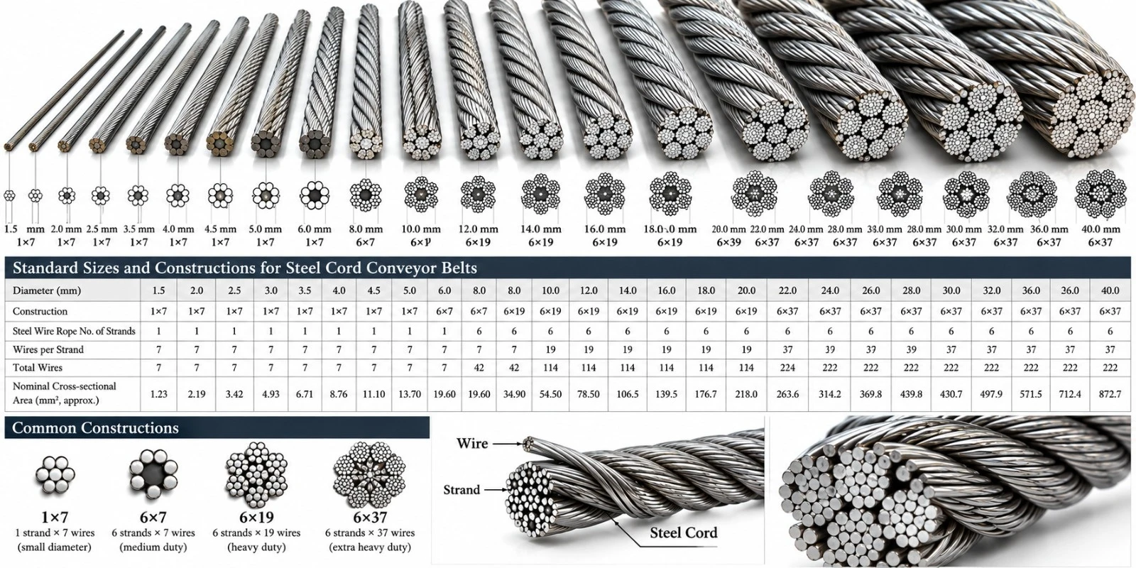
| Belt Class | Nominal Minimum Breaking Strength |
|---|---|
| ST 500 | 500 N/mm |
| ST 630 | 630 N/mm |
| ST 800 | 800 N/mm |
| ST 1000 | 1000 N/mm |
| ST 1250 | 1250 N/mm |
| ST 1400 | 1400 N/mm |
| ST 1600 | 1600 N/mm |
| ST 1800 | 1800 N/mm |
| ST 2000 | 2000 N/mm |
| ST 2250 | 2250 N/mm |
| ST 2500 | 2500 N/mm |
| ST 2800 | 2800 N/mm |
| ST 3150 | 3150 N/mm |
| ST 3500 | 3500 N/mm |
| ST 4000 | 4000 N/mm |
| ST 4500 | 4500 N/mm |
| ST 5000 | 5000 N/mm |
| ST 5400 | 5400 N/mm |
| ST 6300 | 6300 N/mm |
| ST 7500 | 7500 N/mm |
| ST 8000 | 8000 N/mm |
| ST 10000 | 10000 N/mm |
| Class | Typical Cord Diameter d (mm) | Typical Cord Pitch t (mm) | Typical Top Cover S2 (mm) | Typical Bottom Cover S3 (mm) |
|---|---|---|---|---|
| ST500 | 3,0 | 10–12 | 6–10 | 4–6 |
| ST630 | 3,0–3,5 | 10–12 | 6–10 | 4–6 |
| ST800 | 3,7–4,0 | 10–12 | 6–10 | 4–6 |
| ST1000 | 4,0–4,5 | 10–12 | 6–10 | 4–6 |
| ST1250 | 4,5–5,0 | 12–14 | 6–10 | 4–6 |
| ST1600 | 5,0–5,6 | 12–15 | 6–10 | 4–6 |
| ST2000 | 5,6–6,5 | 12–15 | 6–12 | 4–6 |
| ST2500 | 6,5–7,2 | 15–17 | 6–12 | 4–6 |
| ST3150 | 7,5–8,1 | 15–18 | 6–12 | 4–6 |
| ST4000 | 8,5–9,0 | 15–20 | 6–15 | 4–8 |
| ST5000 | 9,5–11,0 | 17–20 | 8–15 | 5–8 |
| ST5400 | 10,5–11,5 | 17–20 | 8–15 | 5–8 |
| ST6300 | Project Engineering | Project Engineering | Project Engineering | Project Engineering |
| ST8000 | Project Engineering | Project Engineering | Project Engineering | Project Engineering |
| ST10000 | Project Engineering | Project Engineering | Project Engineering | Project Engineering |
Reference values are indicative. The exact cord construction, diameter, pitch, cover thickness, overall thickness and belt mass must be confirmed in the approved technical data sheet for each project.
| Product Type | Technical Application |
|---|---|
| Anti-Tear Steel Cord Conveyor Belt | Specially reinforced construction for severe impact, sharp-edged materials and applications with elevated longitudinal tear risk. |
| Steel Cord Belt with Special Transverse Textile Reinforcement | Textile reinforcement arranged transversely to the main longitudinal steel cords, for improved puncture and tear-propagation resistance. |
| Steel Cord Belt with Steel Breaker | Transverse steel reinforcement for severe-service mining, high impact and sharp-lump material applications. |
| Cold-Resistant Steel Cord Belt | Special rubber compounds engineered to retain flexibility and mechanical performance in low-temperature environments. |
| Steel Cord Elevator Belt | Specialized high-strength construction for vertical or steep-lift bulk material handling systems. |
| Heat-Resistant Steel Cord Belt | Special cover and core compounds for elevated-temperature conveyed materials. |
| Flame-Resistant Steel Cord Belt | Safety-engineered compounds for applications requiring controlled flame-propagation characteristics. |
| Oil-Resistant Steel Cord Belt | Compound system engineered for materials containing oils and greases. |
| Low Rolling Resistance Steel Cord Belt | Pulley-side compound engineered to reduce indentation rolling resistance on long-distance overland conveyors. |
Anti-Tear Steel Cord Conveyor Belts are engineered for heavy-duty conveying where large lumps, sharp-edged material, foreign objects or severe loading impact can create a risk of belt penetration and longitudinal ripping. A transverse reinforcement layer distributes localized impact forces and helps restrict the propagation of a longitudinal tear.
Typical applications include hard-rock mining, iron ore, copper ore, coal, limestone, aggregates, ports, steelworks and severe loading points.

Cold-Resistant Steel Cord Belts combine a high-strength steel cord carcass with specially formulated low-temperature rubber compounds. The construction is intended to retain flexibility, impact resistance and cover integrity under freezing ambient conditions. The minimum operating temperature must be selected according to the specified compound and actual project conditions.
Steel Cord Elevator Belts are specialized high-strength constructions for vertical and steep-lift bulk handling. The design must consider bucket loads, fixing loads, dynamic tension, vertical lift, pulley diameters and operating speed. Transverse reinforcement can be incorporated to improve load distribution and tear resistance around the bucket-fixing zones.
| Cover Category | Typical Service |
|---|---|
| Abrasion-resistant | General mining, ore, coal, aggregates and bulk handling. |
| Super Abrasion / Cut & Gouge Resistant | Sharp hard rock and severe mining service. |
| Heat-resistant | Hot clinker, coke and elevated-temperature materials. |
| Oil-resistant | Oily and greasy conveyed materials. |
| Flame-Resistant | Applications requiring defined flame resistance. |
| Cold resistance | Industrial and outdoor low-temperature conveying. |
| Acid / Alkali Resistant | Selected chemical handling services. |
| Low Rolling Resistance | Energy-efficient long-distance overland conveying. |
Steel cord conveyor belts are normally joined using specifically engineered hot-vulcanized splices. Splice geometry, cord arrangement, splice length, materials, cure pressure, temperature and time must be defined for the specific belt class and construction. Correct cord alignment, controlled preparation and documented vulcanization procedures are essential for high dynamic splice performance.
Minimum pulley diameters depend on belt class, cord diameter, splice construction, cover thickness, pulley function and operating tension. Drive, high-tension, low-tension, return and snub pulleys may require different minimum diameters. Transition lengths must be engineered to control edge stress and carcass deformation between the flat and troughed sections of the belt.
Steel cord belts can be integrated with magnetic cord monitoring systems, for detection of cord breaks, internal anomalies and splice condition changes. Depending on conveyor risk, additional systems may include embedded tear-detection loops, longitudinal tear monitoring, surface scanning, belt-mistracking detection, chute-blockage monitoring and metal detection.
| Inspection / Test | Purpose |
|---|---|
| Dimensional Inspection | Verification of belt width, thickness and cover gauges. |
| Steel Cord Geometry | Verification of cord diameter, pitch, count and positioning. |
| Tensile / Breaking Strength | Verification of the specified carcass strength. |
| Cord-to-Rubber Adhesion | Assessment of adhesion and pull-out performance. |
| Cover Physical Properties | Tensile strength, elongation and hardness, where specified. |
| Abrasion Resistance | Assessment of cover wear performance. |
| Aging Performance | Assessment of retained properties after accelerated aging. |
| Flame / Electrical Testing | Applicable to the designated safety grades. |
| Internal Inspection | Magnetic, X-ray or other inspection, when contractually required. |
| Standard | Reference Scope |
|---|---|
| Série ISO 15236 | Steel cord conveyor belts — design, dimensions, requirements, preferred types, safety requirements and vulcanized joints. |
| Série DIN 22131 | Steel cord conveyor belt requirements widely referenced in heavy-duty conveyor engineering. |
| Project / Owner Specification | Mine, EPC, OEM and end-user specifications governing final belt supply and acceptance. |
| Parameter | Required Data |
|---|---|
| Conveyor Geometry | Center distance, rise/fall, incline and curves. |
| Capacity (t/h) | Design and peak throughput. |
| Material | Density, lump size, abrasiveness, sharpness, moisture and temperature. |
| Belt Speed (m/s) | Nominal and maximum operating speed. |
| Tensions | Operating, starting and braking tensions. |
| Pulleys | Diameter, function, lagging and wrap angle. |
| Idlers | Trough angle, diameter and spacing. |
| Environment | Ambient temperature and exposure conditions. |
| Special Protection | Breaker, tear-detection and monitoring requirements. |
| Splice | Required splice class and installation constraints. |
| Field | Designation |
|---|---|
| Product | STEEL CORD CONVEYOR BELT |
| Strength Class | ST [N/mm] |
| Width | [mm] |
| Top cover | [mm] |
| Bottom cover | [mm] |
| Cover Grade | [Compound / Standard] |
| Transverse Reinforcement | [None / Special Fabric / Textile / Steel Breaker] |
| Edge type | [Moulded / Cut, where applicable] |
| Special Features | [Tear Detection / Monitoring / Low Rolling Resistance / Other] |
| Standard | [ISO 15236 / DIN 22131 / Project Specification] |
Example: STEEL CORD CONVEYOR BELT – ST2500 – 1600 mm – 8+6 mm – HIGH ABRASION RESISTANT – SPECIAL TRANSVERSE STEEL BREAKER – MOULDED EDGE – ISO 15236 / PROJECT SPECIFICATION
All values presented in this catalog are intended for preliminary product selection and specification development. Final belt design must be confirmed against the calculated conveyor tensions, safety factors, dynamic analysis where required, pulley diameters, transition lengths, splice efficiency, conveyed material characteristics, environmental exposure and project-specific operating conditions.

Product configurations, materials, structures and selection data for rubber filter belts used in vacuum filtration and dewatering systems.
Technical Note. Dimensions, compounds, construction details and operating limits shall be confirmed against the final application, filtration equipment, process medium and operating conditions before order placement.
World Prime Services operates with a global business perspective, connecting markets, technologies, industrial projects, investors and strategic partners. The company presents more than 20 years of market experience and activities spanning international trade, industrial development, mining, infrastructure, project management, technology and investment consulting.
Within this industrial portfolio, WPS offers rubber filter belt solutions for vacuum filtration and dewatering applications. The product program is structured to support technical selection by process medium, temperature, belt construction, drainage geometry, edge configuration and equipment dimensions.

Rubber filter belt, also referred to as a vacuum belt, is a critical operating component in rubber belt vacuum filters, vacuum belt hydro-extractors and vacuum belt stock washers. The belt functions as the moving support and drainage element of the filtration system, transporting filter cake while enabling liquid removal through the vacuum system.
The belt framework is based on high-strength polyester canvas. Depending on process requirements, cover compounds can be selected for resistance to acid and alkali media, heat, oil and cold. The belt can be produced using integral forming technology to support dimensional stability, smooth running and consistent contact with the filtration equipment.
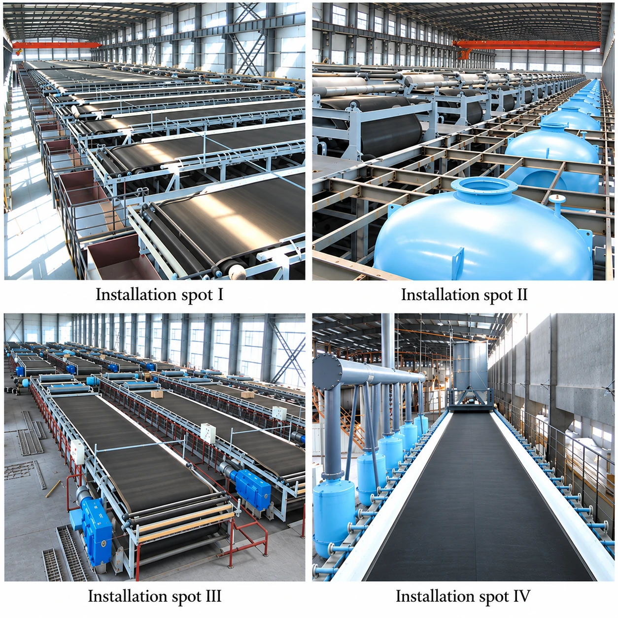
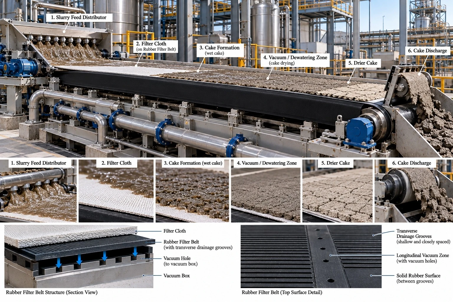
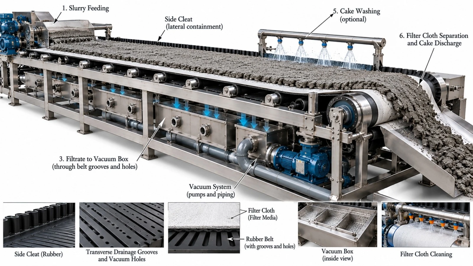
The reference constructions show ordinary, pure-rubber and special filter-belt structures. Typical elements include the belt carcass/framework, top and bottom rubber covers, drainage grooves, displacement holes and capped edges. The exact arrangement is selected according to the filtration machine and process duty.
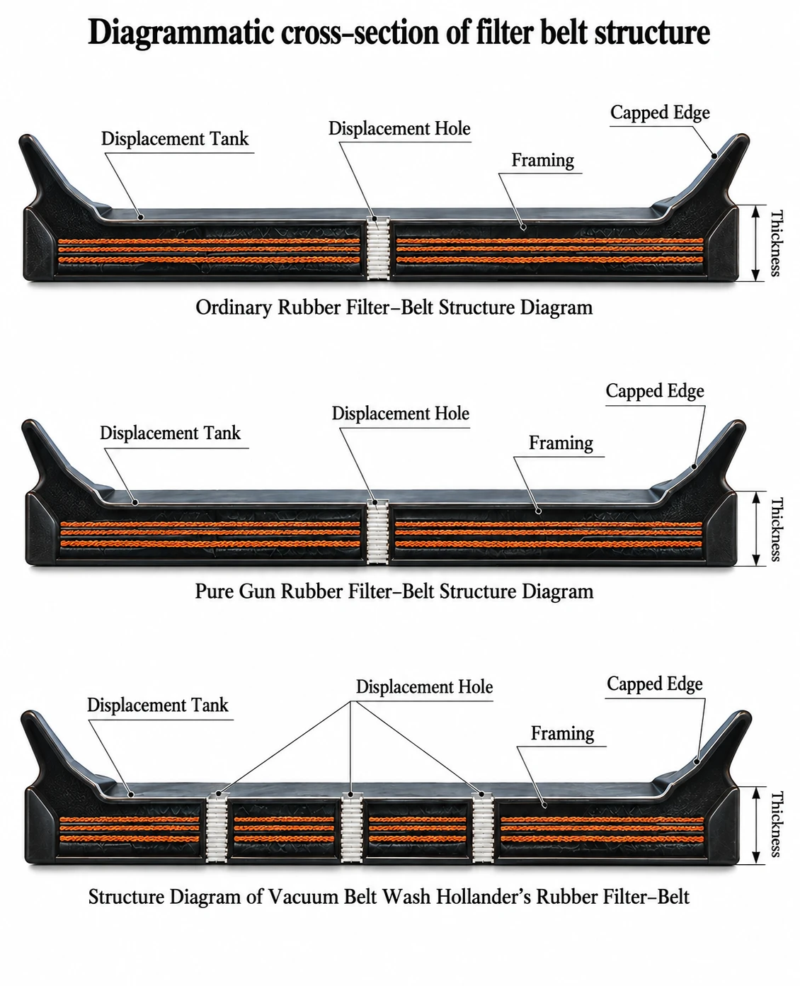
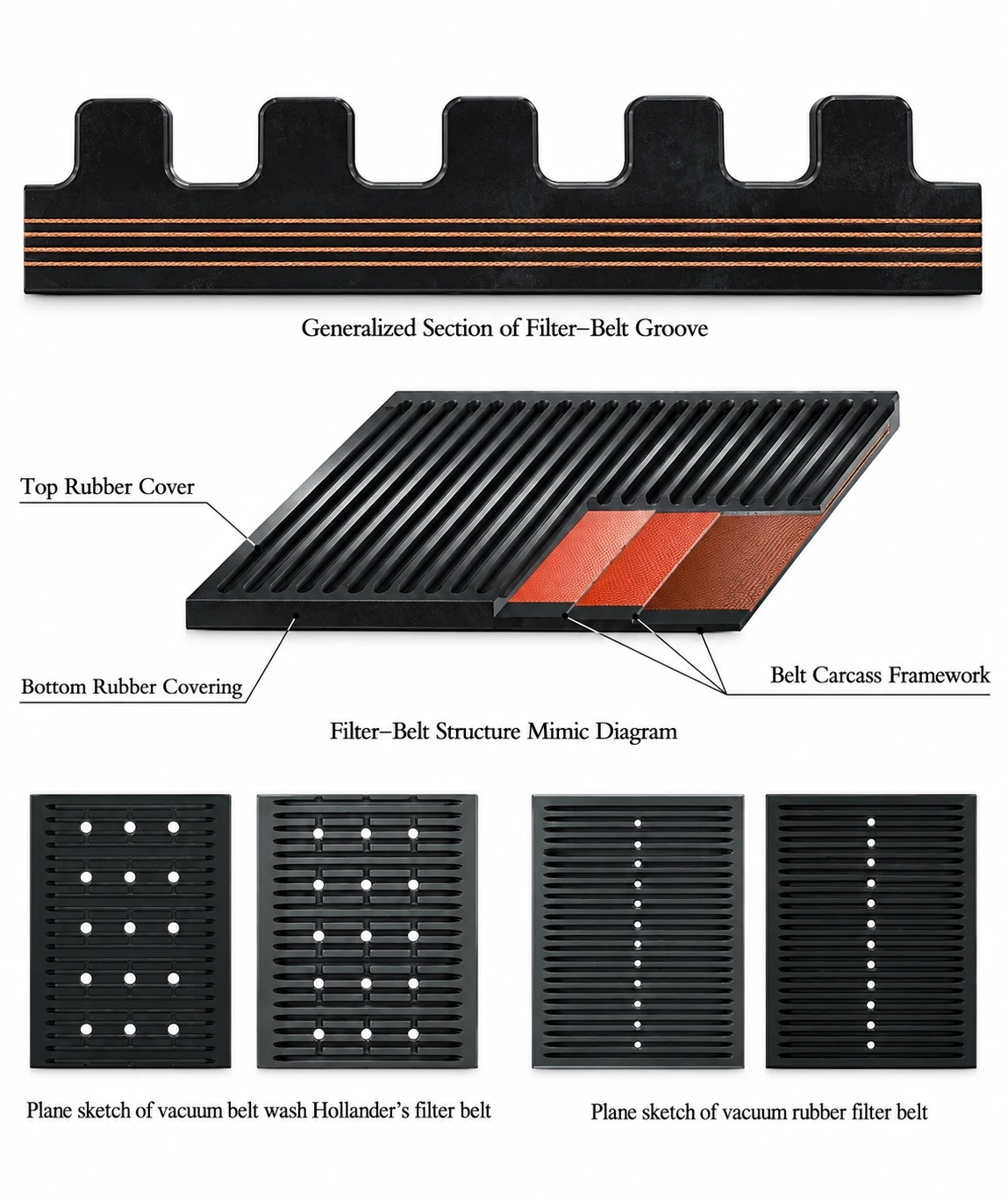
| Element | Function |
|---|---|
| Belt carcass / framework | Provides tensile strength and dimensional support; high-strength polyester canvas is used in the reference construction. |
| Top rubber cover | Process-facing rubber layer selected for chemical, heat, oil or cold resistance. |
| Bottom rubber cover | Protective running-side rubber layer and interface with the filtration equipment. |
| Drainage grooves | Collect and guide filtrate across the belt surface toward drainage points. |
| Displacement / drainage holes | Provide the flow path from the belt surface into the vacuum drainage system. |
| Capped / skirted edge | Supports material containment and edge stability during operation. |
This configuration is intended for filtration duties involving acidic and alkaline process media. Reference applications include phosphate fertilizer, alumina, catalyst processes and flue-gas treatment/desulfurization service.
The cover compound is formulated for acid and alkali resistance, while the framework uses high-strength polyester canvas. The reference catalog notes that the framework offers higher resistance than cotton canvas in acidic and alkaline service. Drainage holes are formed in pure-rubber zones to reduce exposure of the framework to corrosive liquid and to support service life.
The heat resistant filter belt is intended for filtration of elevated-temperature materials. The supplied technical reference identifies an operating range of approximately 80°C to 105°C for this product class.
The reference construction uses an EPDM rubber cover for resistance to heat and aging. The belt framework adopts high-strength polyester canvas, with heat-resistant reinforcement material between the cover rubber and framework. Drainage holes are formed in pure-rubber sections to reduce direct temperature influence on the framework.
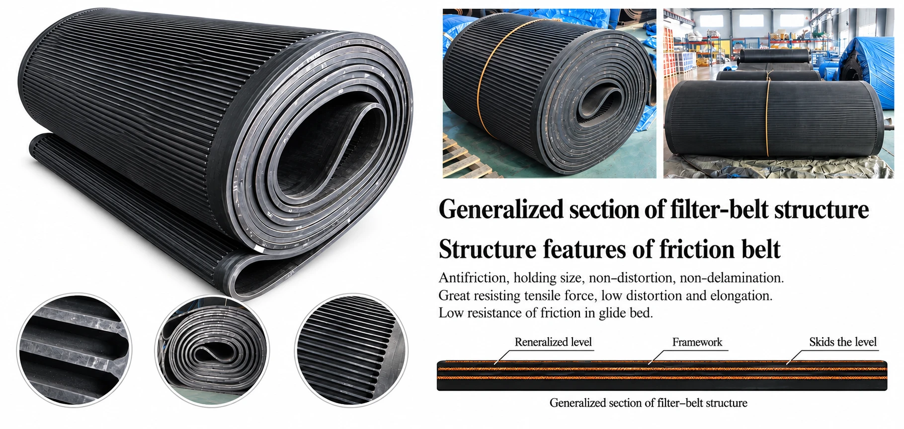
Designed for filtration duties involving oil-bearing materials. The reference cover rubber uses butadiene rubber rich in acrylonitrile, combined with a high-strength polyester-canvas framework. Reported characteristics include low distortion and volume change, high strength and a broad range of industrial uses.
Designed for low-temperature service. The reference catalog identifies a working temperature range from approximately -40°C to +70°C. The framework uses high-strength polyester canvas and the cover compound is based on natural rubber with polybutadiene rubber, providing flexibility, impact resistance and cold resistance.
| Parameter | Required Information |
|---|---|
| Process medium | Oil type / hydrocarbon exposure or low-temperature process medium |
| Temperature | Minimum, normal and maximum operating temperature |
| Equipment | Filter make/model and belt path dimensions |
| Belt geometry | Length, width, thickness, groove profile, drainage-hole layout and edge construction |

The reference type-number system combines: rubber filter belt code number, structure type, nominal belt width, belt thickness, belt length and working-contact-medium code.
| Code Category | Reference Code / Meaning |
|---|---|
| Working contact medium | P - Ordinary medium; S - Acid and alkali medium; W - Hot liquid medium |
| Structure type | A - Ordinary structure; B - Pure rubber structure; C - Special structure |
| Order dimensions | Belt length, belt width and belt thickness shall be provided with the order. |
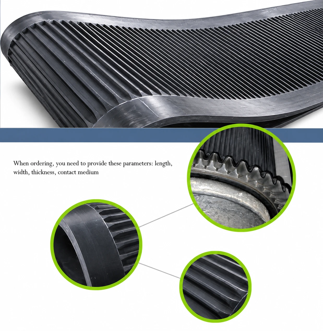
| Item | Machinery | Rubber Filter Belt |
|---|---|---|
| Model | DU11/3300 | DUJ-B-3400 x 38 x 76000-S |
| Length (mm) | 38,900 | 76,000 |
| Width (mm) | 5,000 | 3,400 |
| Height / Thickness (mm) | 3,000 | 38 |
| Filtering area (m²) | 110 | - |
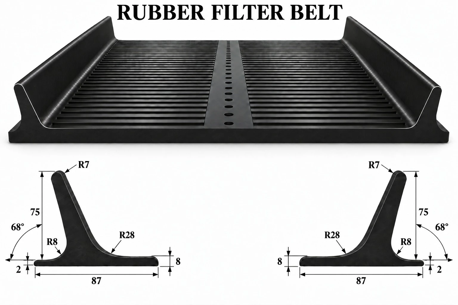
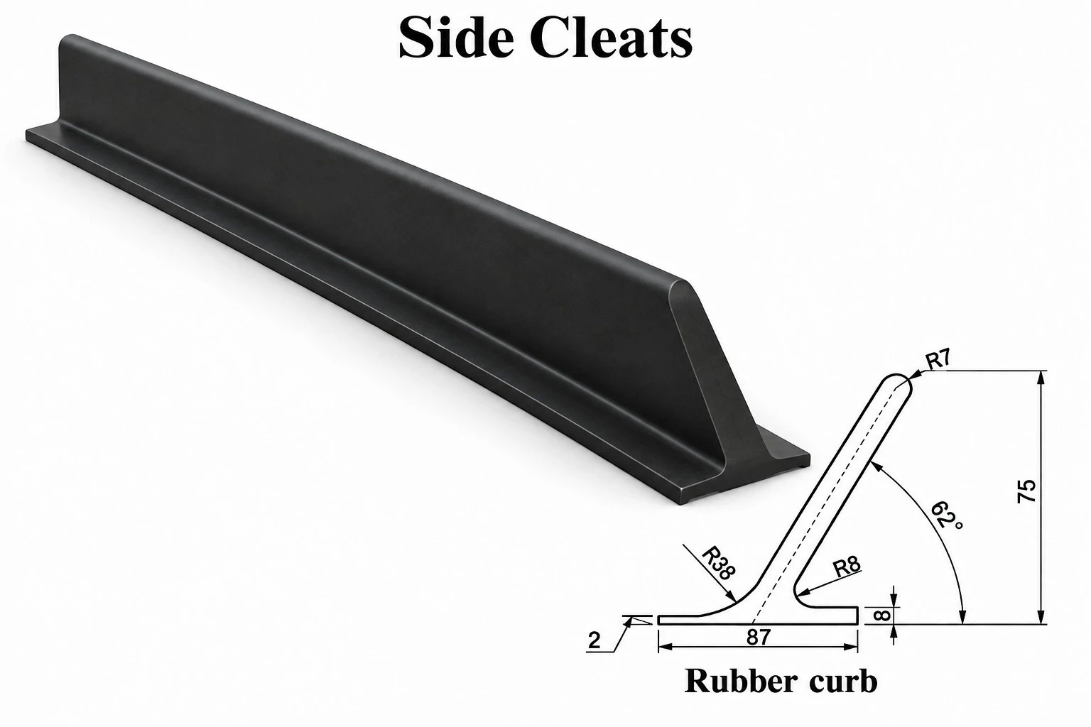
The skirt-edge structure is designed with insulation, elasticity and elongation so that it can flex while passing around rollers. The reference design uses a supporting wave-form structure to improve resistance to distortion and to help maintain the edge profile during operation.
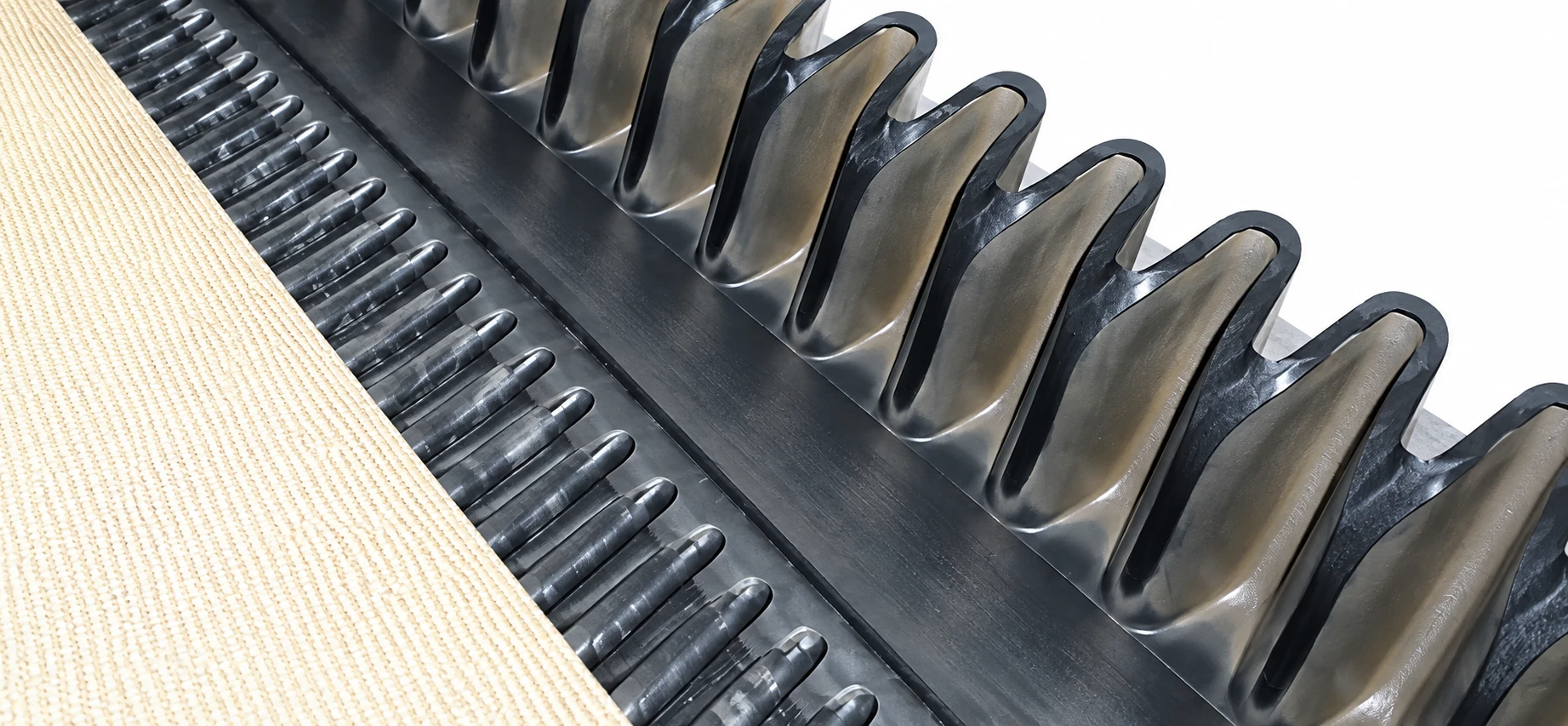
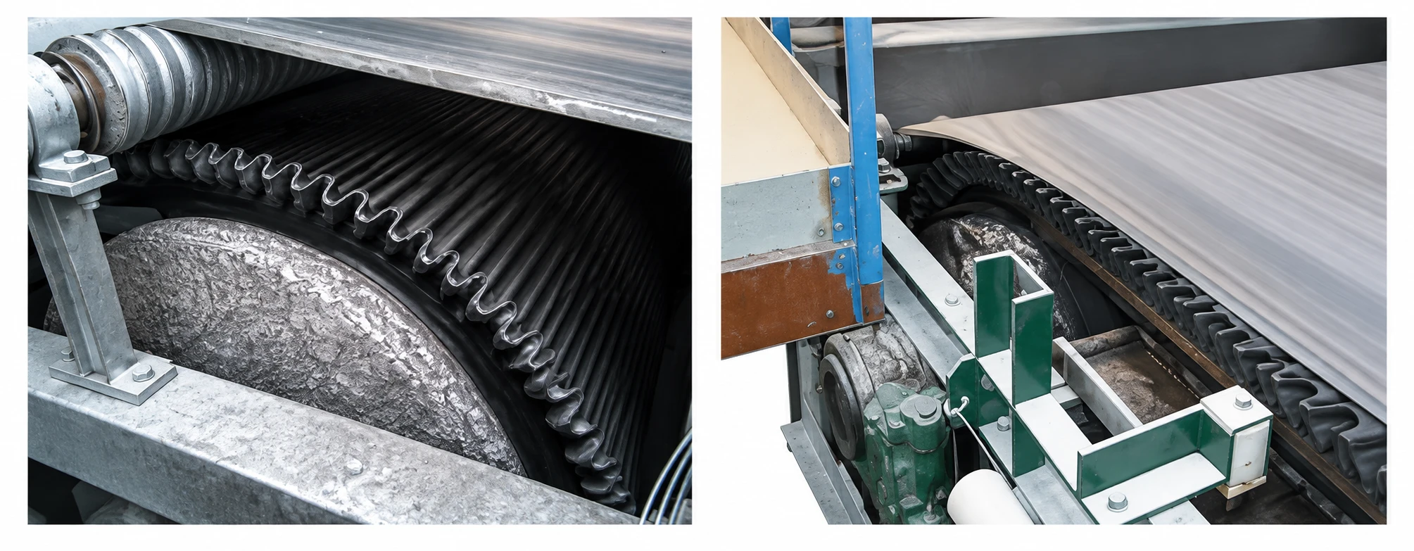
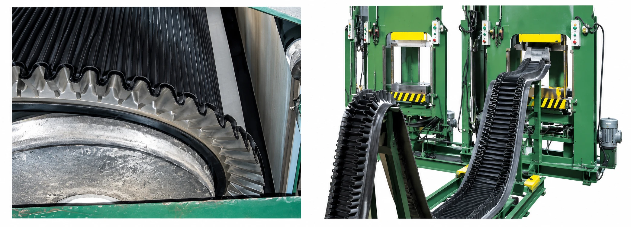
| Method | Reference Description |
|---|---|
| Hot vulcanization | Suitable for high-temperature, strong-acid and strong-alkali working conditions. Provides strong bond capability and longer service life; typically requires factory or controlled workshop processing. |
| Cold bonding | Bonds the rubber belt skirt-edge to the belt body using a bonding system. Convenient for local repair/work; reference material notes shorter service life than hot vulcanization. |

High-Flexibility Multi-Ply Rubber Conveyor Belting for Heavy-Duty Bulk Material Handling
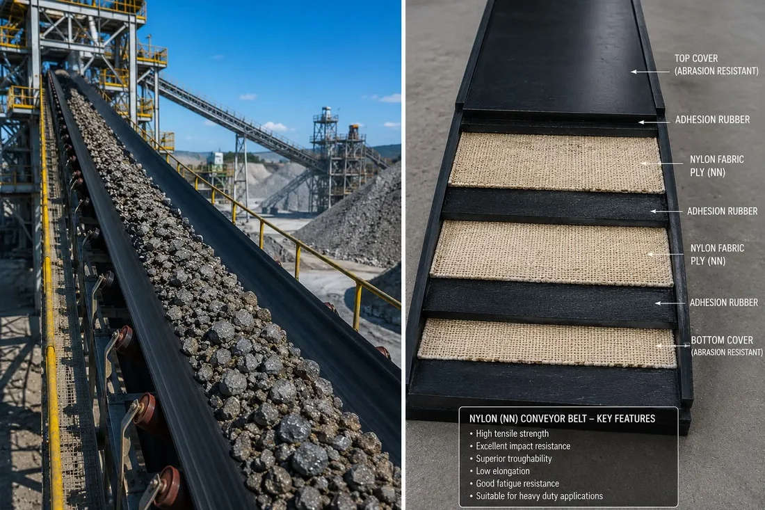
World Prime Services Nylon (NN) Conveyor Belt is a multi-ply rubber conveyor belt using nylon fabric as the principal tension-bearing carcass. The construction is designed for applications requiring high flexibility, strong impact absorption, good troughability and resistance to repeated dynamic flexing.
NN belting is particularly suitable for medium- to heavy-duty bulk handling where impact loading, shorter pulley transitions and frequent bending cycles are important design considerations. Typical applications include mining, quarries, aggregates, cement, ports, metallurgy, power generation and general industrial conveying.
NN denotes a nylon/nylon textile carcass in which nylon yarns are used in both warp and weft directions. The carcass provides high flexibility and strong resistance to shock and impact. Compared with polyester-based EP carcasses, nylon constructions generally exhibit higher elastic elongation and therefore require adequate take-up allowance.
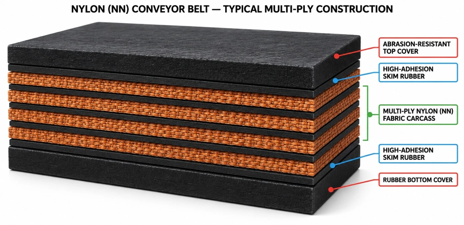
The standard construction combines a wear-resistant top cover, high-adhesion skim rubber, multiple NN fabric plies and a rubber bottom cover. Cover compounds can be selected for abrasion, oil, heat, flame, cold or other project-specific service conditions.
| Component | Engineering Function | Typical Option |
|---|---|---|
| Top cover | Wear and impact protection | Abrasion-resistant / special compound |
| Skim Rubber | Inter-ply bonding and stress transfer | High-adhesion rubber |
| NN Fabric Carcass | Primary tension member | Multi-ply nylon/nylon fabric |
| Bottom Cover | Pulley-side carcass protection | Rubber cover |
| Edge construction | Carcass edge protection | Cut edge / moulded edge |
Common industry NN fabric designations include NN100, NN150, NN200, NN250, NN300 and NN400. These designations are used as carcass strength identifiers in the conveyor-belt market. Final rated belt strength depends on the fabric class, number of plies and approved construction.
| Carcass Designation | Relative Strength Class | Typical Positioning | Engineering Note |
|---|---|---|---|
| NN100 | Light / medium | General bulk handling | Ply count selected by required belt rating |
| NN150 | Medium | Aggregates and industrial duty | Flexible multi-ply construction |
| NN200 | Medium / heavy | Mining, quarry and cement | Common heavy-duty class |
| NN250 | Heavy | High-load bulk handling | Enhanced tension capacity |
| NN300 | Heavy / severe | Mining and demanding industrial systems | Project-specific pulley and take-up design |
| NN400 | Very heavy | High-strength multi-ply applications | Engineering validation required |
High flexibility supports repeated bending around pulleys. Strong impact absorption makes NN belts suitable for lump materials and demanding loading zones. Good troughability supports stable bulk-material containment on troughed idlers. High inter-ply adhesion is essential for dynamic durability.
NN and EP belts should be selected according to conveyor geometry and operating duty. NN is attractive where flexibility and impact resistance are priorities; EP is generally preferred where lower longitudinal elongation and greater dimensional stability are required.
| Characteristic | NN (Nylon/Nylon) | EP (Polyester/Nylon) |
|---|---|---|
| Flexibility | Very high | High |
| Impact absorption | Excellent | Very good |
| Longitudinal elongation | Higher | Lower |
| Dimensional stability | Good | Very good |
| Take-up requirement | Generally greater | Generally lower |
| Typical selection driver | Impact and flexing duty | Low elongation and stable length |
| Special Grade | Primary Duty | Typical Application |
|---|---|---|
| AR | Abrasion-resistant | Mining, quarry, aggregates |
| HR | Heat-resistant | Hot bulk materials |
| OR | Oil-resistant | Oil-contaminated materials |
| FR | Flame retardance | Fire-risk industrial duty |
| FRAS | Flame retardant + antistatic | Coal and specified safety duty |
| CR | Cold resistance | Low-temperature environments |
| CR-CHEM | Chemical resistance | Selected chemical bulk handling |
| Parameter | Catalogue Option / Range | Remarks |
|---|---|---|
| Carcass | NN100 / NN150 / NN200 / NN250 / NN300 / NN400 | Industry carcass designations |
| Ply construction | Multi-ply | Selected by required belt strength |
| Belt width | Approx. 300–3,200+ mm | Project-dependent |
| Top cover | Typically 3–15+ mm | Duty-dependent |
| Bottom cover | Typically 1.5–8+ mm | Duty-dependent |
| Edge | Cut / moulded | Construction-dependent |
| Surface | Smooth standard | Special surfaces by project |
| Splice | Hot vulcanized preferred | Matched to carcass construction |
| Industry | Typical Material | Primary Requirement |
|---|---|---|
| Mining | Ore and overburden | Impact, abrasion and flexibility |
| Quarry & Aggregate | Stone and crushed rock | Impact and wear resistance |
| Cement | Limestone and raw materials | Continuous heavy-duty service |
| Ports & Terminals | Coal, ore and bulk commodities | High capacity and reliability |
| Metallurgy | Minerals and raw materials | Heavy-duty conveying |
| Power Generation | Coal and bulk fuel | Reliable continuous operation |
| Duty | Material Profile | Suggested Carcass Positioning | Protection |
|---|---|---|---|
| Moderate | Fine / granular bulk | NN100–NN150 class | Standard abrasion cover |
| Heavy | Lump aggregate / ore | NN200–NN250 class | Heavy-duty abrasion cover |
| Very Heavy | Large lumps / high impact | NN300–NN400 class | Thick cover + optional breaker |
| Special | Heat, oil, fire or cold exposure | Engineered NN construction | Application-specific compound |
Loading-zone design should minimize uncontrolled drop height and concentrated impact. For sharp or heavy lumps, additional breaker or anti-rip reinforcement may be specified. Skirt-board adjustment and impact-bed condition should be maintained to prevent cover cutting and carcass damage.
Correct troughability depends on belt width, carcass stiffness, ply count and idler trough angle. Conveyor alignment, idler condition and centered loading are critical to stable tracking. Excessive edge tension or poor transition design can shorten carcass life.
Minimum pulley diameter must be selected for the actual belt construction and tension rating. Because nylon carcasses typically have greater elastic elongation than EP carcasses, sufficient take-up travel should be incorporated into the conveyor design.
Hot-vulcanized splicing is generally preferred for critical heavy-duty service. Splice geometry, step length, cover rubber and skim materials must match the belt construction. Mechanical fasteners may be used only where permitted by the application and operating conditions.
Before installation, verify conveyor alignment, pulley condition, idler rotation and loading-zone geometry. Commission the belt under controlled conditions, check tracking and take-up position, then progressively introduce operating load.
| Inspection Point | What to Check | Recommended Action |
|---|---|---|
| Top cover | Cuts, gouges and wear | Repair before carcass exposure |
| Edges | Fraying or edge contact | Correct tracking and structure |
| Splices | Cracks or separation | Engineered inspection / repair |
| Take-up | Insufficient travel | Re-tension or review elongation |
| Idlers | Seized or contaminated rollers | Replace / clean |
| Loading zone | Impact or trapped material | Correct chute and skirt system |
| Control Item | Purpose |
|---|---|
| Belt width / thickness | Dimensional compliance |
| Carcass verification | Confirm NN grade and ply construction |
| Tensile properties | Verify strength performance |
| Elongation | Assess carcass behavior |
| Cover-to-ply adhesion | Verify structural integrity |
| Ply-to-ply adhesion | Verify inter-ply bonding |
| Cover physical properties | Confirm selected compound grade |
| Traceability | Identify production batch |
ISO 14890:2026 is the current international reference for rubber- or plastics-covered conveyor belting of textile construction for general surface use on flat or troughed idlers. The 2026 edition supersedes ISO 14890:2013.
Project specifications may additionally reference applicable DIN, EN, RMA, AS or customer-specific requirements. The exact standard, cover grade and acceptance criteria should be stated at enquiry and purchase-order stage.
| Project / Site | |
| Industry | |
| Conveyed Material | |
| Capacity (t/h) | |
| Bulk Density | |
| Maximum Lump Size | |
| Belt Width (mm) | |
| Belt Speed (m/s) | |
| Center Distance (m) | |
| Inclination (°) | |
| Required NN Grade | |
| Required Belt Rating | |
| Number of Plies | |
| Top Cover (mm) | |
| Bottom Cover (mm) | |
| Required Cover Grade | |
| Edge Type | |
| Breaker / Anti-Rip Requirement | |
| Drive Pulley Diameter | |
| Tail Pulley Diameter | |
| Take-Up Type | |
| Available Take-Up Travel | |
| Splice Requirement | |
| Ambient Temperature | |
| Material Temperature | |
| Applicable Standard | |
| Additional Operating Notes |
| Product Attribute | World Prime Services Nylon (NN) Conveyor Belt |
|---|---|
| Carcass | Multi-ply Nylon/Nylon textile reinforcement |
| Core Strength | High flexibility and impact absorption |
| Typical Classes | NN100, NN150, NN200, NN250, NN300, NN400 |
| Key Industries | Mining, quarry, cement, ports, metallurgy and power |
| Cover Options | Abrasion, heat, oil, flame, cold and chemical-resistant systems |
| Primary Selection Factors | Operating tension, impact, elongation, pulley diameter, take-up and cover duty |
High-Strength, Low-Elongation Multi-Ply Rubber Conveyor Belt for Medium- to Long-Distance Bulk Material Handling

World Prime Services Polyester (EP) Conveyor Belt is a multi-ply rubber conveyor belt engineered for medium- to long-distance bulk material conveying under moderate to heavy operating loads.
The carcass uses EP fabric, in which polyester yarns provide the longitudinal warp reinforcement and nylon/polyamide yarns provide the transverse weft reinforcement. This combination provides low longitudinal elongation, good dimensional stability, strong troughability and reliable resistance to moisture and repeated flexing.
The belt can be supplied with general-purpose, abrasion-resistant, heat-resistant, oil-resistant, cold-resistant, antistatic, flame-retardant and other special-purpose cover compounds.
| Engineering Objective | Operational Benefit |
|---|---|
| Low longitudinal elongation | Reduces take-up travel and improves belt-length stability |
| Tensile strength | Supports medium- and long-distance conveying |
| Good troughability | Supports stable material containment over troughed idlers |
| Moisture-resistant carcass | Suitable for outdoor and wet bulk-handling environments |
| Strong inter-ply adhesion | Supports durability under dynamic flexing |
| Multiple cover grades | Allows adaptation to different conveyed materials and environments |
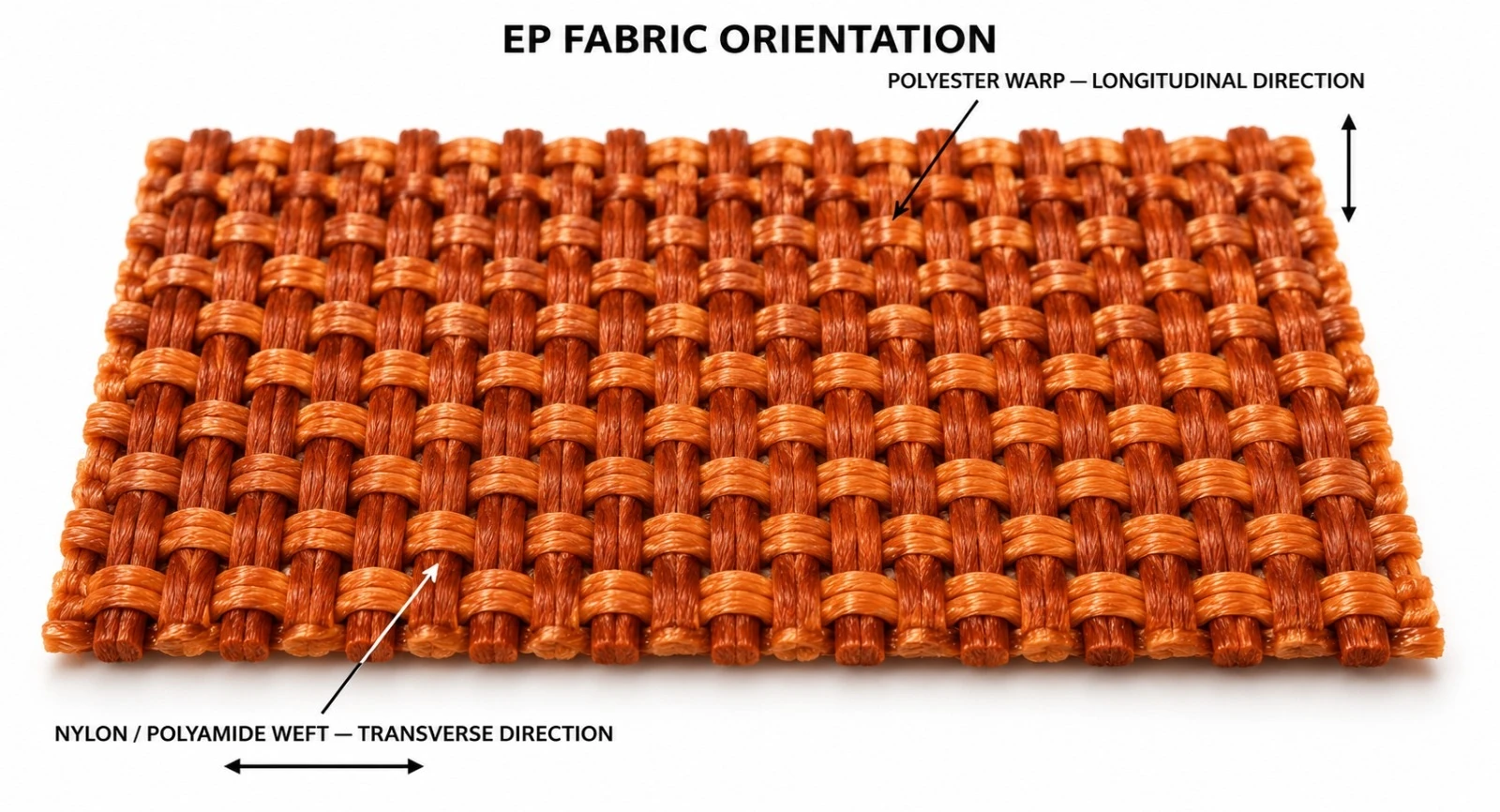
In standard conveyor belt terminology, EP generally denotes a polyester/nylon fabric construction: polyester in the warp direction and nylon (polyamide) in the weft direction. The polyester warp provides tensile strength and low elongation in the belt's travel direction. The nylon weft provides transverse flexibility, impact tolerance and troughing capability.
| Fabric Direction | Typical Fiber | Engineering Function |
|---|---|---|
| Warp — longitudinal | Poliéster | Carries operating tension and limits elongation |
| Weft — transverse | Nylon / polyamide | Provides flexibility, impact absorption and troughing |
| Multi-ply carcass | EP fabric plies | Builds the required rated belt strength |
A professional EP conveyor belt specification should distinguish genuine EP fabric from all-polyester EE constructions. EP denotes a polyester warp combined with a nylon/polyamide weft. An all-polyester carcass is a different textile architecture and can behave differently in elongation, impact response, tear resistance and transition performance.
For procurement and quality-control purposes, the purchase specification should explicitly state the EP fabric construction and require carcass verification, rather than relying solely on a general "polyester conveyor belt" description.
| Term | Typical Meaning | Engineering Note |
|---|---|---|
| EP | Polyester warp / nylon (polyamide) weft | Standard low-elongation fabric for conveyor belts |
| NN | Nylon warp / nylon weft | Higher flexibility and elongation |
| EE | Polyester warp / polyester weft | Different carcass behavior; not equivalent to EP |
| Fabric Conveyor Belt | Generic category | Carcass composition must be specified |

| Component | Engineering Function | Typical Option |
|---|---|---|
| Top cover | Protects the carcass against wear and the conveyed material | General, abrasion, heat, oil, cold or special compound |
| Skim Rubber | Bonds the plies and transfers dynamic load | High-adhesion rubber system |
| EP Fabric Carcass | Primary tension element | Multi-ply polyester/nylon fabric |
| Bottom Cover | Protects the carcass on the pulley side | Standard or special-purpose rubber |
| Edge construction | Protects the carcass edges | Cut edge or moulded edge |
EP-GP Series — General-Purpose Polyester Conveyor Belt. Standard multi-ply construction for general industrial bulk handling.
EP-AR Series — Abrasion-Resistant Polyester Conveyor Belt. Enhanced wear protection for ore, aggregate and abrasive bulk.
EP-HR Series — Heat-Resistant Polyester Conveyor Belt. Application-specific heat-resistant cover for elevated-temperature materials.
EP-OR Series — Oil-Resistant Polyester Conveyor Belt. Oil-resistant cover for oily or grease-contaminated materials.
EP-CR Series — Cold-Resistant Polyester Conveyor Belt. Low-temperature compound for cold climates and storage.
EP-FR Series — Flame-Retardant Polyester Conveyor Belt. Reduced-flammability construction for specified industrial environments.
EP-AS Series — Antistatic Polyester Conveyor Belt. Controlled electrical resistance for static-sensitive applications.
EP-ARX Series — Heavy-Duty Reinforced Polyester Belt. High-strength engineered textile construction for severe service.
| Indicative EP Fabric Class | Relative Positioning | Typical Application |
|---|---|---|
| EP 80 / EP 100 | Light to moderate service | General industrial conveying |
| EP 125 / EP 150 | Moderate service | Agriculture, light aggregate, process industries |
| EP 200 | Medium / heavy service | Quarry, cement and industrial bulk |
| EP 250 | Heavy service | Mining and high-capacity general service |
| EP 300 | Heavy / severe service | High-load industrial conveyors |
| EP 400 | Very heavy textile-belt service | High-strength multi-ply applications |
Final rated belt strength depends on the fabric class, ply count and approved construction. Fabric designation alone should not be treated as the complete belt rating.
| Characteristics | EP Belt Performance |
|---|---|
| Low longitudinal elongation | Low compared to nylon/nylon carcass |
| Dimensional stability | High |
| Troughability | Good to very good, depending on ply count and thickness |
| Moisture resistance | Good |
| Impact resistance | Very good |
| Flex-fatigue resistance | Suitable for continuous industrial service |
| Take-up demand | Generally lower than NN belts |
| Application range | Medium- to long-distance bulk conveying |
| Characteristics | EP Fabric | NN Fabric |
|---|---|---|
| Warp material | Poliéster | Náilon |
| Weft material | Nylon / polyamide | Náilon |
| Longitudinal elongation | Lower | Higher |
| Dimensional stability | Very good | Good |
| Impact absorption | Very good | Excellent |
| Flexibility | High | Very high |
| Typical selection factor | Stable length and lower take-up requirement | Impact and repeated flexing |
| Cover Grade | Primary Property | Typical Application |
|---|---|---|
| GP | General use | Standard industrial bulk handling |
| AR | Abrasion-resistant | Mining, quarry, aggregate |
| HR | Heat-resistant | Hot bulk material |
| OR | Oil-resistant | Oily industrial and agricultural materials |
| CR | Cold resistance | Low-temperature service |
| FR | Flame retardance | Specified fire-risk environments |
| AS | Antistatic | Static-sensitive service |
| CHEM | Chemical resistance | Selected compatible bulk chemicals |
| Parameter | Catalogue Option / Range | Remarks |
|---|---|---|
| Belt width | Approx. 300–3,200+ mm | Project-dependent |
| Carcass | Multi-ply EP fabric | Polyester warp / nylon weft |
| Fabric class | Engineered classes EP 80 to EP 400+ | Project-specific |
| Ply construction | Multi-ply construction | Selected by required belt rating |
| Top cover | Typically 3–20+ mm | Service-dependent |
| Bottom cover | Typically 1.5–10+ mm | Service-dependent |
| Edge | Cut edge / moulded edge | Project-dependent |
| Surface | Standard smooth; special profiles available | Application-specific |
| Splice method | Preferably hot-vulcanized | Matched to carcass construction |
Required belt strength is determined from operating tension, conveyor length, elevation, drive arrangement, capacity, starting conditions and safety factors. Ply count must be selected together with pulley diameter and troughing requirements.
| Input Data | Engineering Purpose |
|---|---|
| Maximum operating tension | Defines the minimum belt tensile rating |
| Conveyor length and elevation | Influences tension and take-up |
| Drive arrangement | Defines traction and starting tension |
| Pulley diameter | Must be compatible with carcass thickness and flexing |
| Trough angle | Requires adequate transverse flexibility |
| Impact severity | May require thicker covers or breaker reinforcement |
| Industry | Typical Material | Primary Requirement |
|---|---|---|
| Mining | Ore and mineral bulk | Strength, abrasion resistance and long-distance reliability |
| Quarry & Aggregates | Crushed stone, sand and gravel | Wear resistance and impact tolerance |
| Cement | Limestone, raw meal and cement materials | Continuous heavy-load service |
| Ports & Terminals | Coal, ore and bulk commodities | High capacity and durability |
| Power Generation | Coal and biomass | Reliable continuous conveying |
| Metallurgy | Raw materials and minerals | Heavy-duty construction |
| Agriculture | Grain and fertilizers | Flexible general-purpose handling |
| General Industry | Industrial bulk materials | Versatile EP carcass performance |
| Duty | Typical Material | Recommended Construction | Cover Selection |
|---|---|---|---|
| Moderate | Fine / granular bulk | Multi-ply EP 100–150 class | GP / light AR |
| Heavy | Aggregate, limestone, ore | EP 200–250 class | AR |
| Very Heavy | Large lumps and high capacity | EP 300–400 class | Heavy AR / optional breaker |
| Hot Service | Clinker and hot bulk | Engineered EP carcass | HR |
| Oily Service | Oil-contaminated material | Engineered EP carcass | OR |
| Cold Service | Outdoor winter bulk | EP carcass | CR |
Troughability depends on belt width, carcass stiffness, overall thickness, ply count and idler trough angle. Transition zones must allow the belt to move gradually between flat-pulley contact and the full troughed shape.
A carcass that is excessively stiff for the selected conveyor can create edge stress, center buckling or unstable tracking. Final transition distance must be engineered from the approved belt construction and conveyor geometry.
| Design Factor | Engineering Impact |
|---|---|
| Drive pulley diameter | Controls flexing stress on the carcass |
| Tail / return pulley diameter | Influences flex-fatigue life |
| Take-up travel | Must accommodate elastic and permanent elongation |
| Pulley alignment | Critical for tracking and edge life |
| Belt tension | Must be sufficient for traction without overloading the carcass |
Hot-vulcanized splicing is generally preferred for critical EP belt service. Splice geometry, step length and materials must be compatible with the belt rating, ply count and cover compound.
| Inspection Point | What to Check | Recommended Action |
|---|---|---|
| Top cover | Cuts, gouges, wear or cracking | Repair before carcass exposure |
| Edges | Fraying or contact with the structure | Correct tracking / alignment |
| Splices | Cracks, lifting or separation | Immediate engineering inspection |
| Take-up | Insufficient travel or excessive tension | Correct the tension adjustment |
| Idlers | Seized or contaminated idlers | Replace / clean |
| Loading zone | Impact or retained material | Correct the chute and skirt system |
| Control Item | Purpose |
|---|---|
| Carcass identification | Confirm the EP fabric construction |
| Belt width / thickness | Dimensional compliance |
| Tensile strength | Verify load-carrying capacity |
| Elongation | Assess dimensional stability |
| Cover tensile properties | Verify the selected compound |
| Cover-to-ply adhesion | Confirm structural integrity |
| Inter-ply adhesion | Verify carcass bonding |
| Abrasion / special-property testing | Verify the cover grade |
| Traceability | Identify the production batch |
| Reference | Relevance |
|---|---|
| ISO 14890:2026 | Rubber- or plastics-covered textile conveyor belts for general use on the surface |
| ISO 283:2023 | Full-thickness tensile strength and elongation test method for textile conveyor belts |
| ISO 252 | Adhesion between the constituent elements of conveyor belts |
| ISO 10247 | Classification of conveyor belt covering properties |
| Customer / Conveyor OEM Specification | Final belt construction and acceptance criteria |
ISO 14890:2026 is the current published international specification for rubber- or plastics-covered textile conveyor belts for general use on the surface over flat or troughed idlers.
| Project / Site | |
| Industry | |
| Conveyed Material | |
| Capacity (t/h) | |
| Bulk Density | |
| Maximum Lump Size | |
| Belt Width (mm) | |
| Belt Speed (m/s) | |
| Center Distance (m) | |
| Lift / Descent (m) | |
| Inclination (°) | |
| Required EP Fabric Class | |
| Required Belt Rating | |
| Number of Plies | |
| Top Cover (mm) | |
| Bottom Cover (mm) | |
| Required Cover Grade | |
| Edge Type | |
| Drive Pulley Diameter | |
| Tail Pulley Diameter | |
| Take-Up Type | |
| Available Take-Up Travel | |
| Operating Ambient Temperature | |
| Material Temperature | |
| Splice Requirement | |
| Applicable Standard / Customer Specification | |
| Additional Operating Notes |
| Product Attribute | World Prime Services Polyester (EP) Conveyor Belt |
|---|---|
| Carcass | Multi-ply polyester warp / nylon (polyamide) weft fabric |
| Core Strength | Low elongation and high dimensional stability |
| Typical Classes | EP 80, EP 100, EP 125, EP 150, EP 200, EP 250, EP 300, EP 400 |
| Key Industries | Mining, quarry, cement, ports, power, metallurgy and general industry |
| Cover Options | General, abrasion, heat, oil, cold, flame-retardant, antistatic and chemical-resistant |
| Selection Basis | Operating tension, belt length, impact, pulley diameter, troughability and cover service |
Lightweight Multi-Ply Rubber Conveyor Belt for Short- to Medium-Distance, Medium-Load Material Handling

World Prime Services Polyester-Cotton (TC) Conveyor Belt is a multi-ply rubber conveyor belt engineered for short- to medium-distance conveying and medium-load bulk material handling.
The load-carrying carcass uses a polyester-cotton textile construction in the warp direction, together with cotton in the weft direction. Compared to conventional cotton-duck belts, the TC construction provides improved mechanical performance, a thinner and lighter carcass, better impact resistance and reduced material and energy consumption in suitable applications.
The product is intended for general-purpose industrial service where moderate tensile demand, reliable flexing, good rubber adhesion and economical operation are required.
| Engineering Objective | Operational Benefit |
|---|---|
| Reinforced polyester-cotton warp | Improved longitudinal strength compared to conventional cotton duck |
| Cotton weft | Good transverse flexibility and troughability |
| Thinner, lighter carcass | Reduced rotating mass and potential energy savings |
| Good impact resistance | Improved durability under moderate impact |
| Strong rubber adhesion | Supports stable multi-ply carcass integrity |
| General-purpose construction | Economical for short- to medium-distance, medium-load conveying |

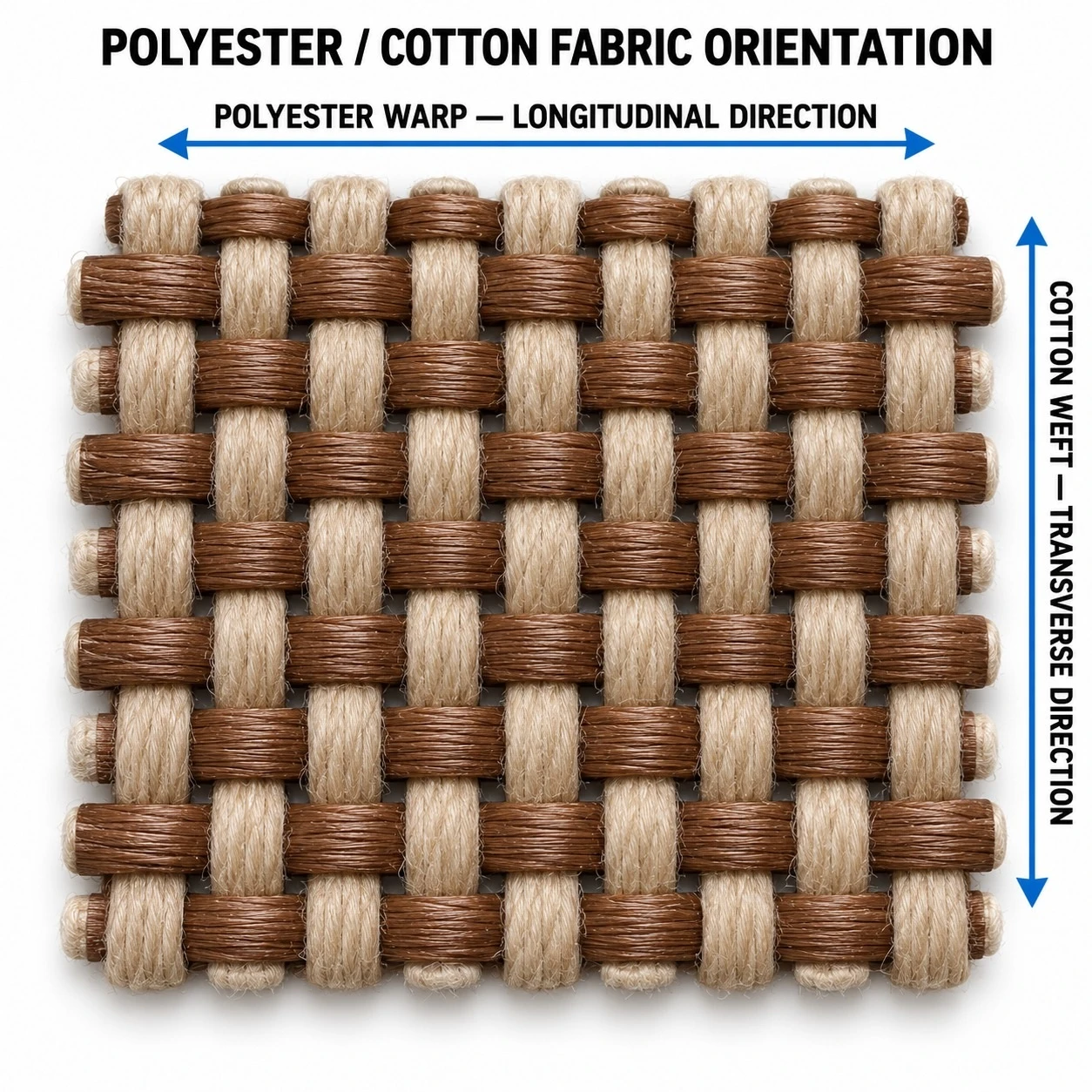
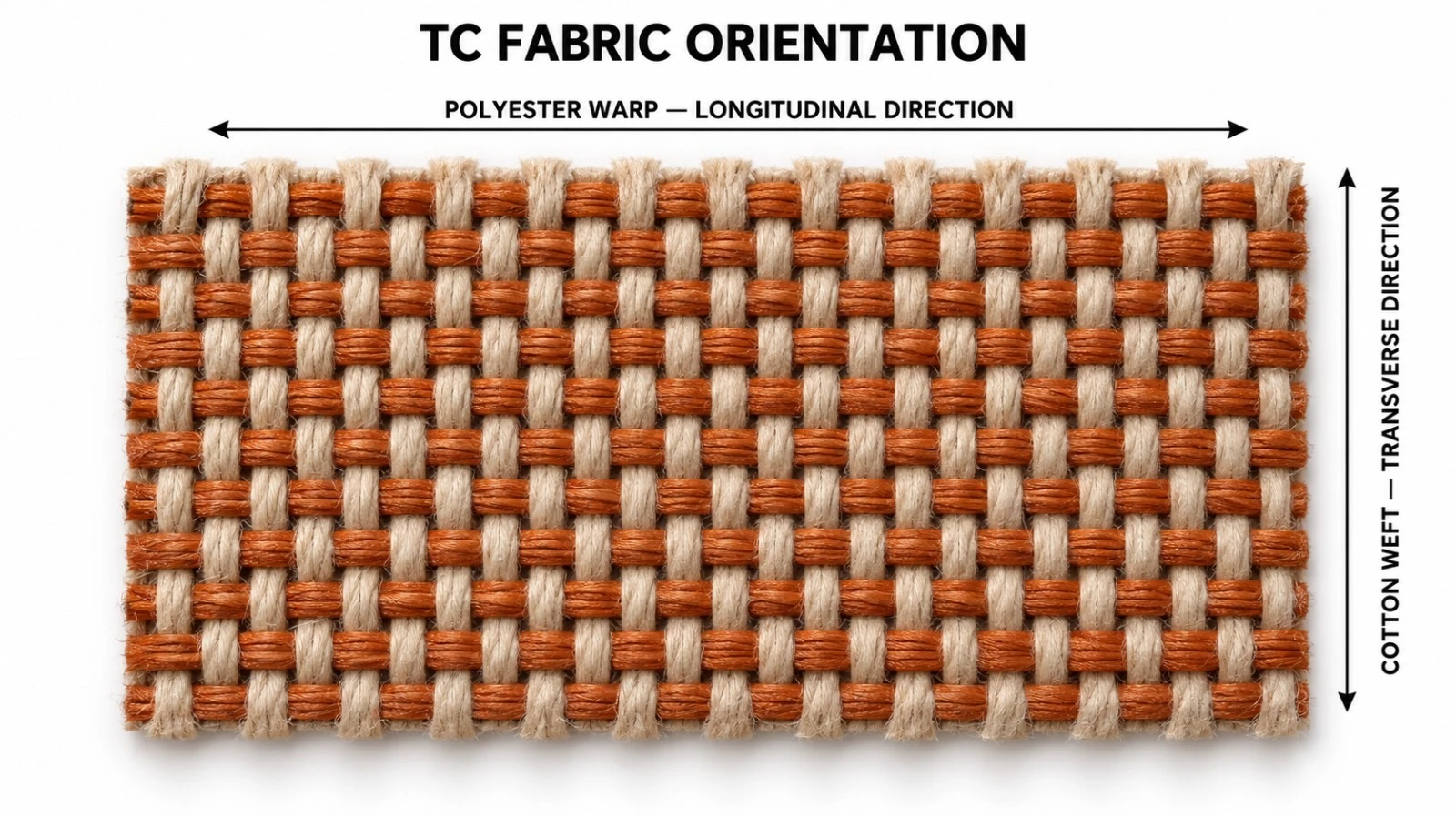
In TC conveyor belt terminology, the carcass is based on a reinforced polyester-cotton warp combined with a cotton weft. The warp direction carries the primary longitudinal load, while the cotton weft provides transverse flexibility and helps the belt conform to troughed idler systems.
TC fabric is positioned between traditional cotton-duck (CC) construction and higher-strength synthetic carcasses such as EP or NN. It is particularly suitable for applications where the full tensile capacity of EP or NN is not required.
| Fabric Direction | Typical Fiber System | Engineering Function |
|---|---|---|
| Warp — longitudinal | Reinforced polyester-cotton yarn system | Tensile load capacity and dimensional stability |
| Weft — transverse | Algodão | Flexibility, troughability and carcass conformability |
| Multi-ply carcass | TC fabric plies | Builds the required belt rating and impact capacity |
| Carcass Type | Typical Construction | Relative Strength | Elongation / Stability | Typical Positioning |
|---|---|---|---|---|
| CC | Cotton warp / cotton weft | Low to moderate | Moderate elongation | Short-distance, light-load service |
| TC | Polyester-cotton warp / cotton weft | Moderate | Improved stability over CC | Short- to medium-distance, medium-load service |
| EP | Polyester warp / nylon weft | Medium to very high | Low elongation | Medium- to long-distance heavy-duty conveying |
| NN | Nylon warp / nylon weft | Medium to very high | Higher elongation, very flexible | Impact-oriented and dynamic-service conveying |
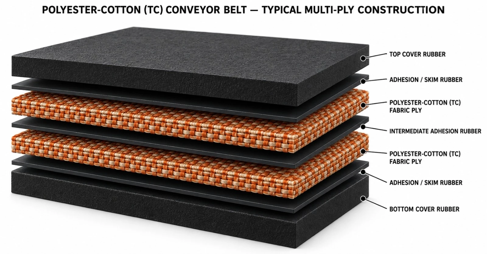
| Component | Engineering Function | Typical Option |
|---|---|---|
| Top Cover Rubber | Protects the carcass against wear and the conveyed material | General-purpose / abrasion-resistant / special compound |
| Adhesion / Skim Rubber | Bonds the cover to the carcass | High-adhesion rubber |
| TC Fabric Ply | Primary load-carrying reinforcement | Polyester-cotton warp / cotton weft |
| Intermediate Adhesion Rubber | Bonds the individual fabric plies | High flex-fatigue adhesion compound |
| Additional TC Fabric Plies | Builds the required belt rating | Multi-ply construction |
| Bottom Cover Rubber | Protects the carcass on the pulley side | General-purpose or special rubber |
TC-GP Series — General-Purpose Polyester-Cotton Conveyor Belt for standard industrial bulk handling.
TC-AR Series — Abrasion-Resistant Polyester-Cotton Conveyor Belt for moderately abrasive service.
TC-HR Series — Heat-Resistant Polyester-Cotton Conveyor Belt for suitable elevated-temperature applications.
TC-OR Series — Oil-Resistant Polyester-Cotton Conveyor Belt for compatible oily or grease-contaminated materials.
TC-CR Series — Cold-Resistant Polyester-Cotton Conveyor Belt for low-temperature service.
TC-AS Series — Antistatic Polyester-Cotton Conveyor Belt for applications requiring controlled electrical resistance.
| Fabric Class | Reference Strength per Ply | Indicative Thickness per Ply | Typical Positioning |
|---|---|---|---|
| TC-70 | Approx. 70 N/mm per ply | Approx. 1.00 mm/ply | General TC construction for medium-load service |
Typical market data for TC-70 belts shows 2- to 6-ply constructions and a rated strength per ply of around 70 N/mm. Final rated belt strength is determined by the approved ply count and the complete belt construction.
| Characteristics | TC Belt Performance |
|---|---|
| Weight | Lighter than comparable conventional cotton-duck construction |
| Carcass thickness | Relatively thin |
| Impact resistance | Improved compared to basic cotton belt |
| Troughability | Good |
| Rubber adhesion | Good |
| Longitudinal strength | Moderate |
| Take-up demand | Suitable for short- to medium-distance systems |
| Primary economic advantage | Economical general-purpose solution |
| Parameter | Catalog Option / Typical Range | Remarks |
|---|---|---|
| Fabric type | TC-70 | Polyester-cotton warp / cotton weft |
| Ply count | Typically 2–6; higher project-specific ply counts possible | Selected by required belt rating |
| Reference strength per ply | Approx. 70 N/mm | Typical industry reference |
| Ply thickness | Approx. 1.00 mm/ply | Typical reference |
| Belt width | Approx. 400–2,200+ mm | Manufacturing- and project-dependent |
| Top cover thickness | Approx. 1.5–8 mm typical | Service-dependent |
| Bottom cover thickness | Approx. 0–4.5 mm typical | Service-dependent |
| Roll length | Up to approx. 300 m in common market references | Width- and handling-dependent |
| Edge construction | Cut edge / moulded edge | Application-dependent |
| Splice | Hot-vulcanized / approved mechanical | Project-dependent |
| Cover Grade | Primary Property | Typical Application |
|---|---|---|
| GP | General use | Standard industrial bulk materials |
| AR | Abrasion-resistant | Moderately abrasive bulk |
| HR | Heat-resistant | Suitable hot-material applications |
| OR | Oil-resistant | Oil-contaminated materials |
| CR | Cold resistance | Low-temperature service |
| AS | Antistatic | Static-sensitive service |
| Industry | Typical Material | Primary Requirement |
|---|---|---|
| Agriculture | Grain, seeds and fertilizers | Economical medium-load conveying |
| Cement & Construction Materials | Limestone, additives and light raw materials | General-purpose durability |
| Power & Utilities | Selected coal or biomass service | Moderate-load conveying |
| Warehousing & Terminals | General bulk commodities | Reliable short- to medium-distance handling |
| Manufacturing | Industrial raw materials | Versatile general-purpose service |
| Quarry Support Applications | Selected aggregates and fines | Moderate abrasion resistance |
| Duty | Material Profile | Recommended Construction | Cover Selection |
|---|---|---|---|
| Light | Fine / granular material | 2–3-ply TC | GP |
| Moderate | General bulk material | 3–4-ply TC | GP / AR |
| Medium Load | Selected aggregate, fertilizer and industrial bulk | 4–6-ply TC | AR / project-specific |
| Warm Material | Compatible elevated-temperature bulk | Engineered TC construction | HR |
| Oily Material | Compatible oil-contaminated bulk | Engineered TC construction | OR |
The correct number of TC fabric plies is selected from operating tension, conveyor length, capacity, elevation, starting conditions, pulley diameter and service factor.
| Design Input | Engineering Purpose |
|---|---|
| Operating tension | Determines the minimum belt rating |
| Conveyor length | Influences elongation and take-up requirement |
| Conveyed load | Determines the carcass strength requirement |
| Pulley diameter | Must be compatible with overall carcass thickness |
| Trough angle | Requires sufficient transverse flexibility |
| Impact severity | May require thicker covers or additional plies |
TC belts must be matched to appropriate pulley diameters to avoid excessive flexing stress. The cotton-containing transverse structure provides good flexibility, but the final minimum pulley diameter must be confirmed from the overall belt thickness, ply count and splice construction.
Take-up travel must be sufficient for the elastic and permanent elongation expected in the selected TC carcass. Precise alignment is important to prevent edge wear and premature carcass damage.
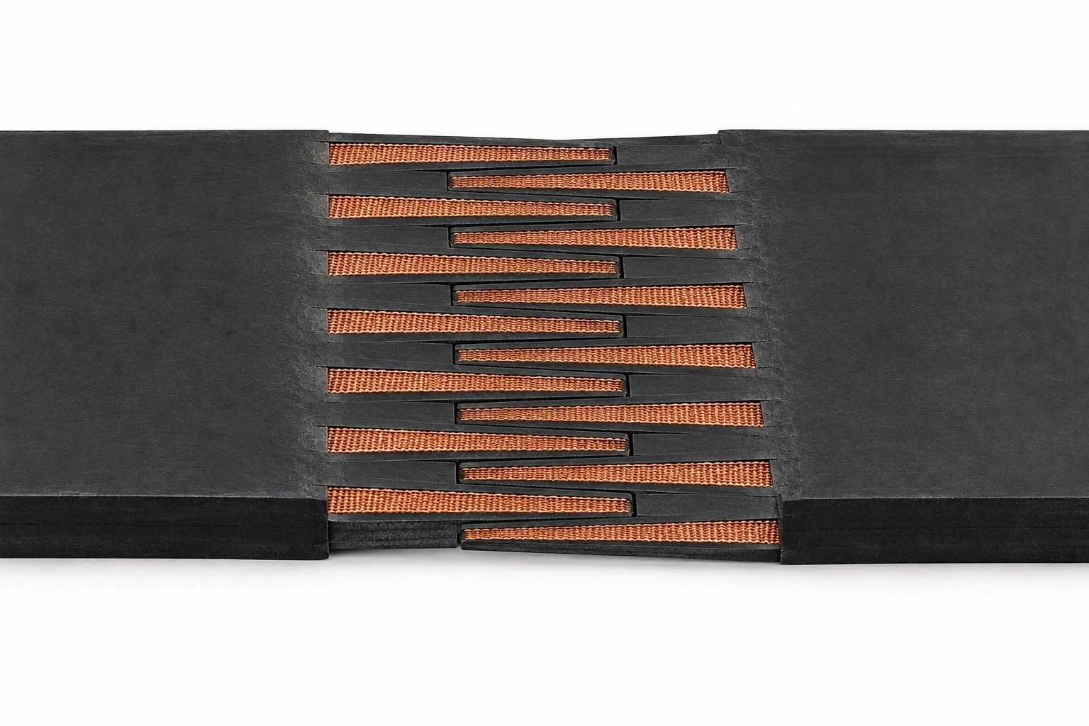

Hot-vulcanized splicing is preferred for critical continuous-service installations. Mechanical fasteners may be used where permitted by the application.
| Inspection Point | What to Check | Recommended Action |
|---|---|---|
| Top cover | Cuts, wear or cracking | Repair before carcass exposure |
| Edges | Fraying or contact with the structure | Correct tracking and alignment |
| Splices | Lifting, cracking or separation | Immediate inspection |
| Take-up | Insufficient travel or excessive tension | Adjust per engineering data |
| Idlers | Seizing or contamination | Clean / replace |
| Loading zone | Impact or retained material | Correct chute and skirt conditions |
| Control Item | Purpose |
|---|---|
| Fabric identification | Confirm the TC carcass construction |
| Belt width / thickness | Dimensional compliance |
| Tensile strength | Verify carcass performance |
| Elongation | Assess dimensional stability |
| Cover physical properties | Verify the selected cover compound |
| Cover-to-ply adhesion | Confirm structural integrity |
| Inter-ply adhesion | Verify bonding between plies |
| Traceability | Identify the production batch |
| Reference | Relevance |
|---|---|
| ISO 14890 | Rubber- or plastics-covered textile conveyor belts for general use on the surface |
| ISO 283 | Full-thickness tensile strength and elongation test method |
| ISO 252 | Adhesion between the constituent elements of conveyor belts |
| ISO 10247 | Classification of conveyor belt covering properties |
| Customer / Conveyor OEM Specification | Final belt construction and acceptance criteria |
| Project / Site | |
| Industry | |
| Conveyed Material | |
| Capacity (t/h) | |
| Bulk Density | |
| Maximum Lump Size | |
| Belt Width (mm) | |
| Belt Speed (m/s) | |
| Center Distance (m) | |
| Inclination (°) | |
| Required TC Fabric Class | |
| Required Belt Rating | |
| Number of Plies | |
| Top Cover (mm) | |
| Bottom Cover (mm) | |
| Required Cover Grade | |
| Edge Type | |
| Drive Pulley Diameter | |
| Tail Pulley Diameter | |
| Take-Up Type | |
| Available Take-Up Travel | |
| Operating Temperature | |
| Material Temperature | |
| Splice Requirement | |
| Applicable Standard / Customer Specification | |
| Additional Operating Notes |
| Product Attribute | World Prime Services Polyester-Cotton (TC) Conveyor Belt |
|---|---|
| Carcass | Reinforced polyester-cotton warp / cotton weft |
| Reference Fabric Class | TC-70 |
| Primary Positioning | Short- to medium-distance, medium-load conveying |
| Key Benefits | Lighter carcass, improved impact resistance, good troughability and economical service |
| Typical Industries | Agriculture, construction materials, utilities, terminals and general manufacturing |
| Cover Options | General use, abrasion, heat, oil, cold and antistatic |
| Selection Basis | Operating tension, ply count, conveyor length, pulley diameter and cover service |
PVC and PVG Flame-Resistant / Antistatic Conveyor Belt
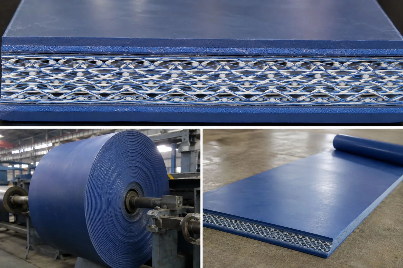
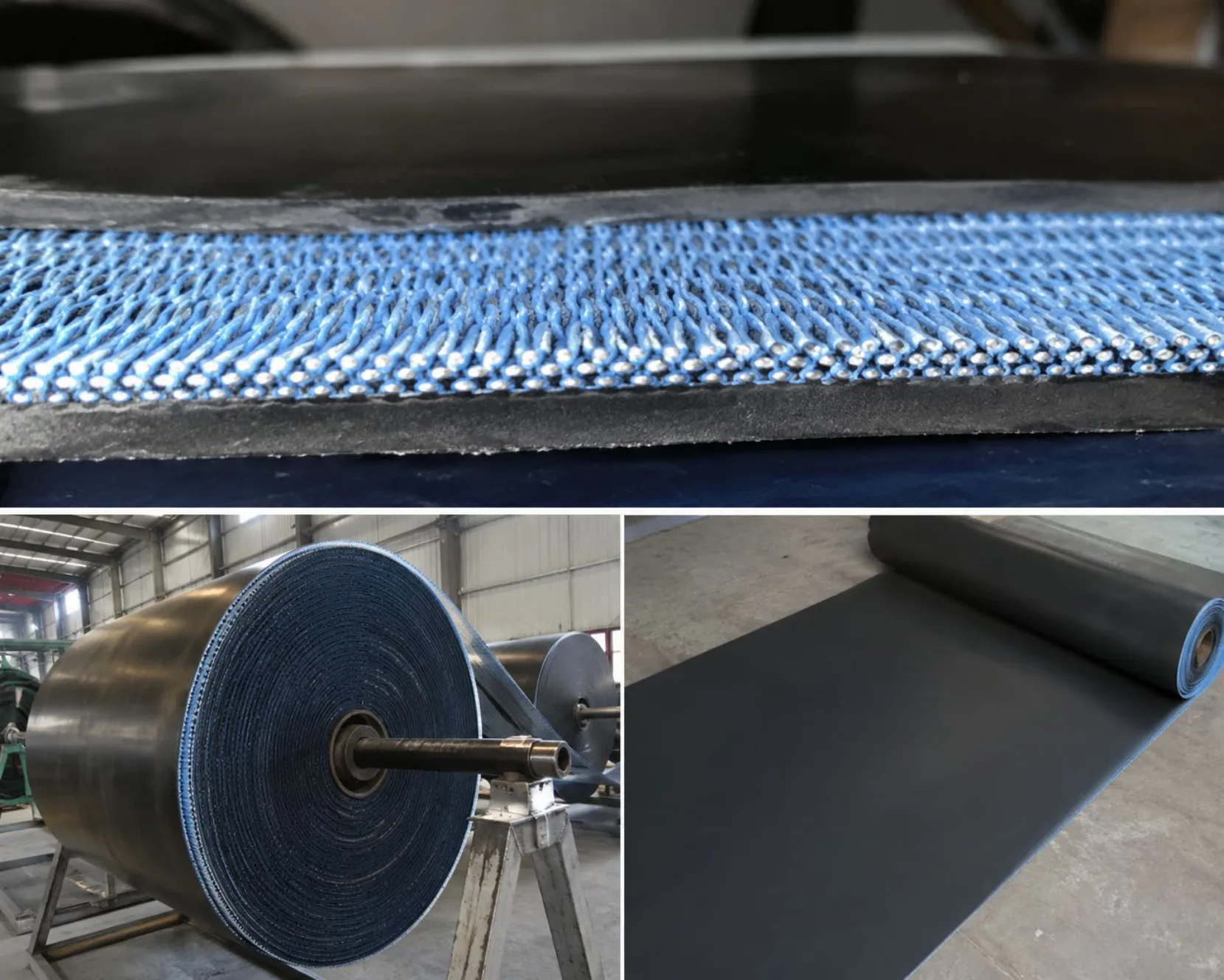
World Prime Services Solid Woven Conveyor Belt is engineered for demanding bulk material conveying, where high tensile strength, low elongation, carcass integrity, impact resistance and controlled safety performance are required. The integral solid-woven carcass is impregnated with PVC compound, creating a compact structure with excellent resistance to moisture penetration, edge damage and ply separation.
The product line is available in PVC and PVG constructions. PVC belts use PVC-impregnated solid-woven carcass technology, with PVC surface covers. PVG belts combine the solid-woven carcass with rubber- or nitrile/PVC-based covers, for enhanced abrasion, impact, moisture and traction performance.

| Component | Construction | Function |
|---|---|---|
| Top cover | PVC- or PVG-based compound | Wear, impact and environmental protection. |
| Solid Woven Carcass | Integral interwoven warp/weft reinforcement, PVC-impregnated | Carries tension and distributes impact without conventional ply separation. |
| Carcass Impregnation | PVC compound throughout the woven reinforcement | Improves adhesion, moisture resistance and structural integrity. |
| Bottom Cover Rubber | PVC or PVG compound | Pulley-side protection and friction performance. |
| Integrated Edge | Impregnated solid-woven edge | Reduces moisture penetration and edge separation. |
The PVC Solid Woven Conveyor Belt is primarily intended for dry or controlled environments requiring a compact, flexible and safety-oriented belt. Typical applications include underground coal conveying, power generation and selected industrial material-handling systems requiring specified flame-resistant and antistatic performance.
| Parameter | Typical Description |
|---|---|
| Cover System | PVC top and bottom covers |
| Typical Cover Reference | 0.8 + 0.8 mm for common strength classes |
| Typical Incline Guide | Up to approximately 16°, subject to material and conveyor design |
| Key Benefits | Low elongation, good troughability, moisture resistance, integral carcass |
| Primary Duty | Underground coal handling and safety-sensitive bulk |
The PVG Solid Woven Conveyor Belt uses an integral solid-woven carcass impregnated with PVC, with enhanced rubber- or nitrile/PVC-based covers. This construction provides improved abrasion resistance, impact performance, wet-service traction and durability under more severe operating conditions.
| Parameter | Typical Description |
|---|---|
| Cover System | Rubber / nitrile-PVC-based top and bottom covers |
| Typical Cover Reference | 1.5 + 1.5 mm; 2.0 + 2.0 mm for higher classes |
| Typical Incline Guide | Up to approximately 20°, subject to material and conveyor design |
| Key Benefits | Improved resistance to abrasion, impact, moisture and slippage |
| Primary Duty | Mining and severe industrial bulk material conveying |
| Class | Warp / Weft Strength (N/mm) | PVC Cover (mm) | PVG Cover (mm) | Typical Width (mm) | Min. Pulley Diam. (mm) |
|---|---|---|---|---|---|
| 680S | 680 / 265 | 0,8 + 0,8 | 1,5 + 1,5 | 650–1600 | 320 |
| 800S | 800 / 280 | 0,8 + 0,8 | 1,5 + 1,5 | 650–1600 | 400 |
| 1000S | 1000 / 300 | 0,8 + 0,8 | 1,5 + 1,5 | 650–1600 | 500 |
| 1250S | 1250 / 350 | 0,8 + 0,8 | 1,5 + 1,5 | 650–1600 | 500 |
| 1400S | 1400 / 350 | 0,8 + 0,8 | 1,5 + 1,5 | 650–1600 | 630 |
| 1600S | 1600 / 400 | 0,8 + 0,8 | 2,0 + 2,0 | 650–1600 | 750 |
| 1800S | 1800 / 400 | 0,8 + 0,8 | 2,0 + 2,0 | 650–1600 | 800 |
| 2000S | 2000 / 400 | 0,8 + 0,8 | 2,0 + 2,0 | 650–1600 | 800 |
| 2240S | 2240 / 450 | 0,8 + 0,8 | 2,0 + 2,0 | 650–1600 | 1000 |
| 2500S | 2500 / 450 | Project-Specific | Project-Specific | Project-Specific | 1000 |
Solid woven belt is widely used in underground mining because the integral carcass can be combined with specially formulated impregnation and cover compounds to meet defined flame-resistant and antistatic requirements. Compliance, certification and test methods must be specified for the destination market and confirmed for the exact belt construction supplied.
| Region / Market | Commonly Referenced Standard |
|---|---|
| Germany | Série DIN 22109 |
| Australia | AS 4606 |
| Canada | CSA M422 |
| United States | Applicable MSHA / Title 30 requirements |
| China | Série MT 914 |
| Other Markets | Applicable national mining and fire-safety standards |
| Industry | Typical Service |
|---|---|
| Underground Coal Mining | Coal and run-of-mine material conveying. |
| Mining & Minerals | Selected ores and mineral products. |
| Potash Mining | Potash ore and mineral handling. |
| Power Generation | Coal and fuel handling systems. |
| Metallurgy | Selected raw materials and process feed. |
| Industrial Bulk Handling | Continuous conveying requiring low elongation and carcass integrity. |
Solid woven belts can be joined using approved mechanical fastening or hot-finger / vulcanized splice engineering systems, depending on belt type, strength class, conveyor service and safety requirements. Splice geometry, materials and procedures must be compatible with the selected PVC or PVG construction.
| Parameter | Required Information |
|---|---|
| Material | Name, bulk density, moisture, abrasiveness and temperature. |
| Capacity (t/h) | Normal and peak capacity in t/h or m³/h. |
| Conveyor Geometry | Center distance, vertical lift and incline. |
| Belt | Width, speed and calculated operating tension. |
| Pulley System | Drive, tail, return and take-up pulley diameters. |
| Environment | Underground/surface, wet/dry and ambient conditions. |
| Safety | Required flame-resistant, antistatic or mine-approval standard. |
| Construction | PVC or PVG, strength class and cover thickness. |
| Splice | Mechanical or vulcanized/hot-finger splice requirement. |
SOLID WOVEN – [PVC/PVG] – [BELT CLASS] – [BELT WIDTH] – [TOP/BOTTOM COVER] – [SAFETY STANDARD] – [SPLICE REQUIREMENT]
Order designation examples:
SOLID WOVEN – PVC – 1000S – 1000 mm – 0.8/0.8 mm – FR/AS – MECHANICAL SPLICE
SOLID WOVEN – PVG – 1250S – 1200 mm – 1.5/1.5 mm – FR/AS – HOT FINGER SPLICE
SOLID WOVEN – PVG – 1600S – 1400 mm – 2.0/2.0 mm – AS 4606 – VULCANIZED SPLICE
| Designation Field | Description |
|---|---|
| PVC / PVG | Cover type and belt construction |
| Belt Class | Nominal tensile strength class, e.g. 680S, 800S, 1000S, 1250S, 1400S, 1600S, 1800S, 2000S, 2240S or 2500S |
| Belt Width | Nominal belt width in millimeters |
| Top / Bottom Cover | Specified top and bottom cover thickness |
| Safety Standard | Required flame-resistant, flame-retardant and/or antistatic standard |
| Splice Requirement | Mechanical, hot-finger, vulcanized or project-specific splice system |
All dimensions and performance values presented are typical engineering reference values. Final belt class, cover construction, width, pulley diameter, splice design and operating limits must be confirmed through application-specific engineering review and applicable safety or regulatory requirements, before manufacturing.
High-Strength Belt for Vertical Conveying in Bucket Elevator Systems

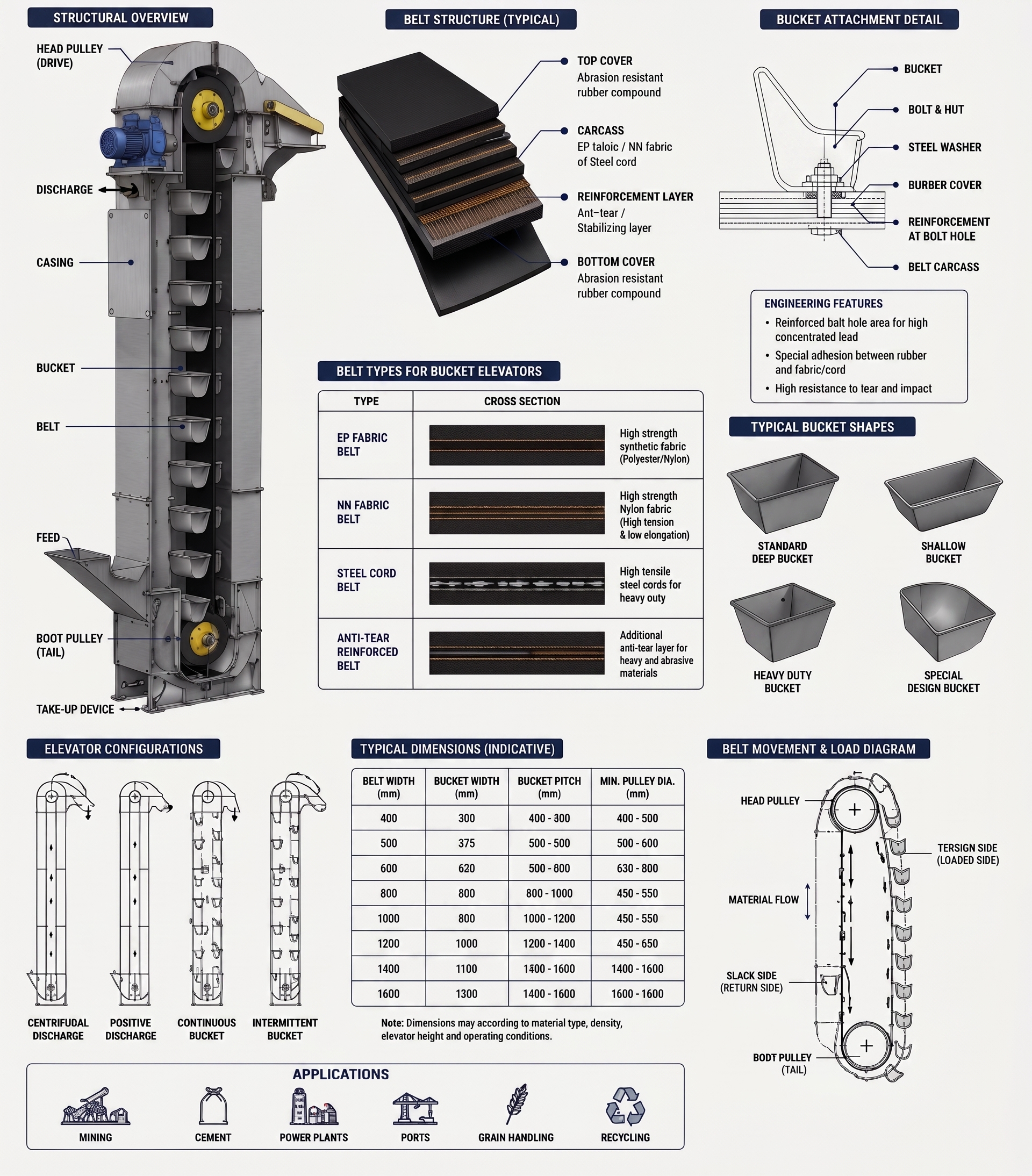
World Prime Services Bucket Elevator Belt is engineered for continuous or steep-incline vertical lifting of material, where buckets are mechanically fixed to the belt. The belt is designed to carry continuous vertical tension load, repeated flexing at the pulleys, stress concentrated around the bucket bolt holes, dynamic loading and the combined suspended mass of the belt, buckets and conveyed material.
The product range includes reinforced EP and NN fabric constructions, as well as steel cord elevator belts for high-lift, high-capacity, low-elongation service. Depending on the application, construction may incorporate tear-resistant reinforcement, reinforced bucket-fixing zones and special cover compounds resistant to abrasion, heat, oil, flame or static charge.
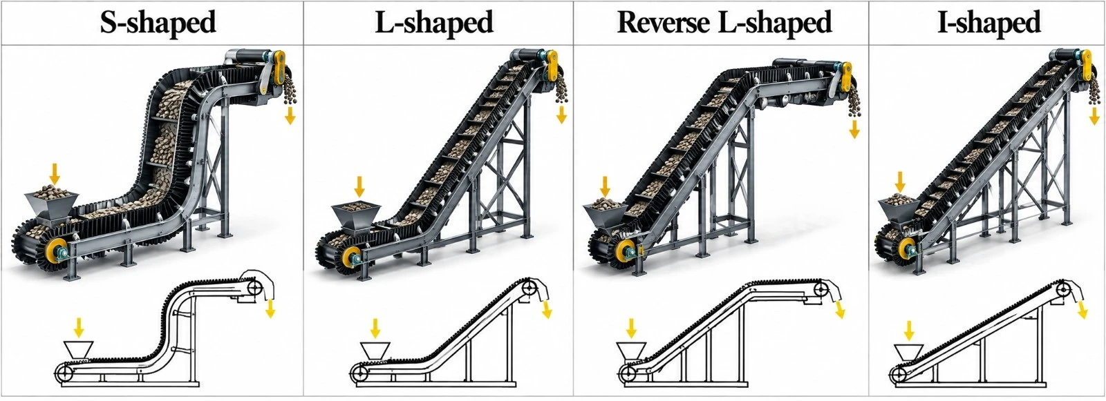
| Engineering Objective | Operational Benefit |
|---|---|
| High longitudinal tensile strength | Supports the vertical load of the buckets and bulk material |
| Low elongation | Improves bucket alignment, tracking and take-up stability |
| High bolt pull-out resistance | Reduces local damage around the bucket fixing holes |
| High cover-to-carcass adhesion | Maintains structural integrity under repeated flexing |
| Tear-resistant reinforcement | Helps limit damage propagation from the fixing holes |
| Fabric and steel cord options | Covers moderate to extreme lift and tension requirements |
Buckets are fixed to the elevator belt at defined pitches. Bulk material is loaded at the boot section, captured by the buckets and lifted vertically to the head pulley, where it is discharged by centrifugal action or by gravity, depending on the elevator design.
Unlike a conventional horizontal belt, a bucket elevator belt continuously carries the suspended weight of the belt, buckets and material. The belt is also subjected to concentrated fixing forces, repeated flexing at the head and boot pulleys, and dynamic tension variations. Carcass selection, pulley diameter, bucket pitch and take-up design are therefore critical.
| Component | Engineering Function | Typical Options |
|---|---|---|
| Top cover | Bucket-fixing side and primary carcass protection | Abrasion-, heat-, oil- or flame-resistant rubber |
| High-adhesion skim rubber | Transfers load between the cover and the reinforcement | High-bonding rubber system |
| Primary tension carcass | Carries the vertical operating tension | EP fabric, NN fabric or steel cord |
| Tear-resistant reinforcement | Improves tear resistance at bolt holes and damaged zones | Textile breaker or transverse steel/textile reinforcement |
| Bottom cover | Protects the reinforcement on the pulley side | Abrasion-resistant or special-purpose compound |
| Bucket-fixing zone | Localized fixing region | Factory-drilled or field-punched per approved hole pattern |
| Series | Description |
|---|---|
| BE-EP | EP Fabric Bucket Elevator Belt — low-elongation, multi-ply polyester/nylon construction for grain, fertilizer, cement, minerals and general vertical conveying. |
| BE-NN | Nylon Fabric Bucket Elevator Belt — flexible, impact-tolerant construction for medium-duty systems requiring good fatigue performance. |
| BE-ST | Steel Cord Bucket Elevator Belt — high-tensile, very-low-elongation construction for tall elevators, heavy buckets, dense bulk materials and high-capacity systems. |
| BE-AR | Tear-Reinforced Elevator Belt — fabric or steel cord construction with additional transverse reinforcement to reduce tear propagation from bucket holes and localized damage. |
| BE-X | Severe-Service Elevator Belt, Engineered — custom construction for extreme lift height, hot clinker, sharp minerals or critical continuous-process service. |
EP fabric is widely used in bucket elevator belts because it combines relatively low elongation with good dimensional stability, fatigue resistance and rubber adhesion. Multi-ply constructions distribute the bucket loads and provide good resistance to repeated flexing at the pulleys.
| Fabric Construction | Typical Strength Class | Characteristics | Typical Use |
|---|---|---|---|
| EP 315–500 | Moderate vertical load | Flexible, stable and cost-effective | General industrial elevators |
| EP 630–1000 | Heavy vertical load | Higher tensile capacity and reduced elongation | Cement, fertilizer and minerals |
| EP 1250–1500+ | Very heavy fabric service | High tensile support around bucket zones | Large-capacity elevators |
| NN / reinforced fabric | Impact-oriented service | High flexibility and fatigue resistance | Selected medium-duty systems |
Steel cord bucket elevator belts are selected when lift height, bucket weight or material density generate tensile loads beyond practical textile constructions. Steel cords provide very high tensile strength and low elongation, improving bucket pitch consistency and limiting take-up travel.
| Steel Cord Class | Indicative Minimum Pulley Diameter* | Typical Duty |
|---|---|---|
| ST 500–630 | Approx. 600 mm | Basic steel cord elevator service |
| ST 800–1000 | Approx. 650–750 mm | Medium/high lift |
| ST 1250–1600 | Approx. 850–1,000 mm | Heavy vertical conveying |
| ST 1800–2500 | Approx. 1,200–1,500 mm | High-tension, high-capacity systems |
| ST 2800–3150 | Approx. 1,550–1,700 mm | Very high lift and dense materials |
| ST 4000–5000 | Approx. 1,850–2,100 mm | Extreme-tension engineered systems |
*Industry-indicative reference values. The final pulley diameter must be confirmed per the approved belt construction and elevator design.
| Parameter | Catalogue Option / Range | Remarks |
|---|---|---|
| Belt width | Approx. 300–2,200+ mm | Final width per elevator and bucket design |
| Textile carcass | EP / NN multi-ply | Strength selected from total vertical tension |
| Fabric tensile class | Approx. EP 315 to EP 1500+ | Higher dedicated engineered grades available |
| Steel cord carcass | Approx. ST 500 to ST 5000 | High-lift and high-tension applications |
| Top cover thickness | Typically 3–10+ mm | Bucket-fixing side |
| Bottom cover thickness | Typically 2–8+ mm | Pulley side |
| Tear-resistant reinforcement | Optional textile / steel transverse system | Recommended for severe fixing service |
| Edge construction | Cut edge / moulded edge | Project-specific |
| Bucket holes | Factory-drilled / field-punched per approved pattern | Hole layout must be dedicated engineered |
| Special properties | Abrasion, heat, oil, flame, antistatic | Application-dependent |
| Design Factor | Engineering Impact |
|---|---|
| Head pulley diameter | Controls flexing stress at the discharge pulley |
| Boot pulley diameter | Influences reverse flexing and fatigue |
| Take-up travel | Compensates for elastic elongation and operational movement |
| Pulley lagging | Supports traction and reduces slippage |
| Belt speed | Affects centrifugal discharge and dynamic load |
| Bucket pitch | Influences load distribution and throughput |
| Parameter | Engineering Requirement |
|---|---|
| Hole diameter | Match the bucket bolt specification with controlled clearance |
| Hole spacing | Maintain consistent bucket pitch and alignment |
| Edge distance | Provide adequate material between the holes and the belt edge |
| Row spacing | Distribute load without excessive stress concentration |
| Reinforcement location | Align the reinforcement with the bucket-fixing zone |
| Bolt torque | Prevent loosening without crushing the belt carcass |
| Washer / backing plate | Use sufficient bearing area to distribute the fixing load |
Elevator capacity depends on bucket width, bucket volume, bucket pitch, belt speed, fill rate and discharge efficiency. Belt strength must be selected from the maximum operating tension, not from throughput alone.
| Bucket Width (mm) | Indicative Throughput at 100% Fill (m³/h)* | Indicative Throughput at 75% Fill (m³/h)* |
|---|---|---|
| 160 | 38 | 28 |
| 200 | 55 | 41 |
| 250 | 87 | 65 |
| 315 | 127 | 95 |
| 400 | 197 | 148 |
| 500 | 287 | 215 |
| 630 | 465 | 349 |
| 800 | 665 | 499 |
| 1000 | 935 | 701 |
| 1250 | 1.166 | 874 |
| 1400 | 1.310 | 980 |
| 1600 | 1.443 | 1.102 |
| 1880 | 1.613 | 1.211 |
| 2000 | 1.808 | 1.352 |
*Industry reference figures for engineering comparison purposes only. Actual throughput depends on bucket geometry, pitch, belt speed, material density and fill behavior.
| Industry | Typical Materials | Primary Requirement |
|---|---|---|
| Cement | Cement, clinker, limestone | High tensile strength, heat and abrasion resistance |
| Mining & Minerals | Ore, concentrate, aggregate | Heavy load capacity and tear protection |
| Fertilizers | Potash, phosphate, granular fertilizer | Chemical and abrasion resistance |
| Grain & Food Processing | Grain, seeds, sugar | Stable bucket alignment and clean handling |
| Power Plants | Coal, biomass, ash | Continuous-service reliability |
| Ports & Terminals | Minerals and bulk commodities | High capacity and durability |
| Recycling | Industrial solids and processed materials | Impact and tear resistance |
| Cover Family | Primary Duty | Typical Application |
|---|---|---|
| BE-AR | Abrasion-resistant | Cement, aggregates and minerals |
| BE-HR | Heat-resistant | Clinker and hot bulk materials |
| BE-OR | Oil-resistant | Oily materials and selected industrial products |
| BE-FR | Flame-resistant | Selected regulated and coal applications |
| BE-AS | Antistatic | Dust-sensitive industrial environments |
| BE-CR | Chemical-resistant | Fertilizers and chemically aggressive materials |
| Inspection Point | What to Check | Recommended Action |
|---|---|---|
| Bucket holes | Cracking, elongation or tear initiation | Repair or replace before propagation |
| Buckets and bolts | Loose fixings, deformation, missing hardware | Retighten or replace |
| Belt edges | Fraying, delamination or contact with the casing | Correct tracking and repair |
| Splice / fixing | Movement, cracking or separation | Immediate dedicated engineered inspection |
| Head / boot pulleys | Lagging wear, slippage or misalignment | Correct promptly |
| Take-up system | Insufficient travel or uneven tension | Restore correct operating tension |
| Carcass | Exposed fabric or steel cords | Immediate repair or replacement |
| Control Item | Purpose | Typical Stage |
|---|---|---|
| Belt width and thickness | Dimensional compliance | Final inspection |
| Carcass verification | Confirm EP/NN/ST construction | Production |
| Cover tensile / elongation | Verify compound properties | Laboratory |
| Adhesion test | Confirm cover-to-carcass bonding | Laboratory |
| Steel cord adhesion | Verify cord bonding where applicable | Laboratory |
| Bolt-hole / tear-resistance evaluation | Assess fixing-zone integrity | Project-specific |
| Visual inspection and traceability | Detect defects and identify the production batch | Final inspection / dispatch |
| Reference | Relevance |
|---|---|
| ISO 14890 | Textile conveyor belts for general-use construction and mechanical properties |
| ISO 15236 (série) | Steel cord conveyor belts — design and mechanical requirements |
| DIN / EN / customer-specific bucket elevator design requirements | Pulley, belt, bucket and elevator system engineering |
| Project-specific bolt-hole and splice qualification | Fixing-zone performance and vertical tension |
Bucket elevator belts must be dedicated engineered as part of the complete elevator system, since concentrated fixing loads and continuous vertical tension cannot be evaluated from the belt's nominal tensile strength alone.
| Project / Site | |
| Industry | |
| Conveyed Material | |
| Material Temperature | |
| Bulk Density | |
| Capacity (t/h) | |
| Elevator Height (m) | |
| Center Distance (m) | |
| Belt Width (mm) | |
| Belt Speed (m/s) | |
| Bucket Width / Volume | |
| Bucket Pitch | |
| Number of Bucket Rows | |
| Bucket Material / Weight | |
| Bolt Diameter | |
| Bolt-Hole Pattern | |
| Required Carcass Type | |
| Required Belt Strength | |
| Top / Bottom Cover (mm) | |
| Head Pulley Diameter | |
| Boot Pulley Diameter | |
| Take-Up Travel | |
| Splice / Fixing Requirement | |
| Tear-Resistant Reinforcement Required? | |
| Heat Resistance Required? | |
| Oil Resistance Requirement | |
| Chemical Resistance Required? | |
| Flame Resistance Requirement | |
| Antistatic Requirement | |
| Applicable Standard | |
| Additional Operating Notes |
High-Grip Industrial Rubber Conveyor Belt for Inclined Unit Handling
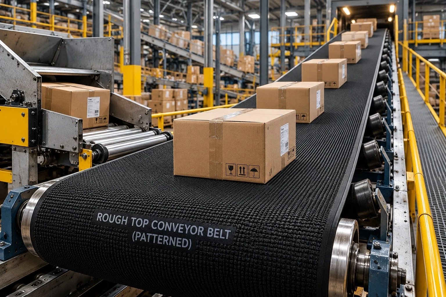
Rough Top (Patterned) Conveyor Belts are engineered with a patterned surface that provides exceptional grip and superior material handling performance, even on steep inclines and in wet or muddy conditions.
The raised pattern on the top cover increases friction between the belt and the conveyed material, preventing slippage and ensuring stable, efficient, and continuous operation.
These belts are ideal for industries that require reliable conveying solutions for bulk materials on inclined conveyors.
Professional product catalog for the selection and specification of rough top patterned rubber conveyor belts, intended for packaged goods, bags, cardboard boxes, parcels and other unit loads requiring enhanced surface grip.
| Attribute | Detail |
|---|---|
| Product Type | Rough Top / Patterned Rubber Conveyor Belt |
| Carcass Options | EP (Polyester-Nylon), NN (Nylon-Nylon), textile constructions dependent on application |
| Top Surface | Moulded or stamped high-friction rough top rubber pattern |
| Bottom Construction | Rubber-covered bottom or bare back / fabric back |
| Typical Use | Inclined conveying, packaging, warehousing, bag handling, baggage, wood and paper products |
| Color Options | Black, tan, blue, green and other compounds/colors subject to production availability |
Technical note: the values presented in this catalog are typical industry selection ranges, compiled for product definition and quotation. Final belt construction, cover grade, dimensions, pulley requirements and the permitted operating angle must be confirmed based on the actual conveyor and service conditions.
World Prime Services Rough Top Conveyor Belt is a high-friction, textile-reinforced rubber conveyor belt engineered to improve load stability on flat and inclined conveyor systems. The moulded or stamped top surface provides enhanced grip to reduce slippage, rollback and load shifting, while the resilient rubber profile contributes cushioning and vibration absorption during conveying.
The product is especially suitable for unit loads and packaged materials, where a smooth belt may not provide sufficient friction. Typical conveyed products include paper and polymer bags, cardboard boxes, parcels, crates, baggage, light industrial components, wood products, glass packaging and other fragile or deformable products.

| Feature | Technical Benefit |
|---|---|
| High-friction rough top profile | Improves contact and load retention on inclined or accelerating conveyors |
| Resilient rubber surface | Cushions the conveyed products and helps absorb vibration and impact |
| Textile carcass | Provides tensile strength, flexibility and controlled elongation |
| Rubber-back option | Suitable for conventional pulley/idler conveyor arrangements |
| Bare back / fabric back option | Suitable for slider-bed systems, where lower bottom-side friction is preferred |
| Multiple colors | Supports application differentiation and selected industrial handling requirements |

Two main backing constructions are available. The rubber-covered bottom configuration provides a conventional protected bottom cover for contact with pulleys and idlers. The bare back or fabric back configuration leaves the textile surface exposed on the bottom and is commonly selected for slider-bed conveyors or applications requiring lower bottom-side drag.
| Component | Available Configuration | Function |
|---|---|---|
| Top profile | Stamped / moulded rough top rubber pattern | High grip and non-slip contact with the load |
| Top cover | Wear-resistant rubber compound; special compounds by application | Protects the carcass and provides resilient load support |
| Carcass | EP or NN textile plies | Tensile strength, load support and flexibility |
| Inter-ply skim | Rubber adhesion layers | Maintains inter-ply adhesion and structural integrity |
| Bottom side | Rubber cover or bare fabric | Selected according to pulley/idler or slider-bed conveyor design |
| Edge type | Cut edge or moulded edge | Selected according to belt construction and operating environment |
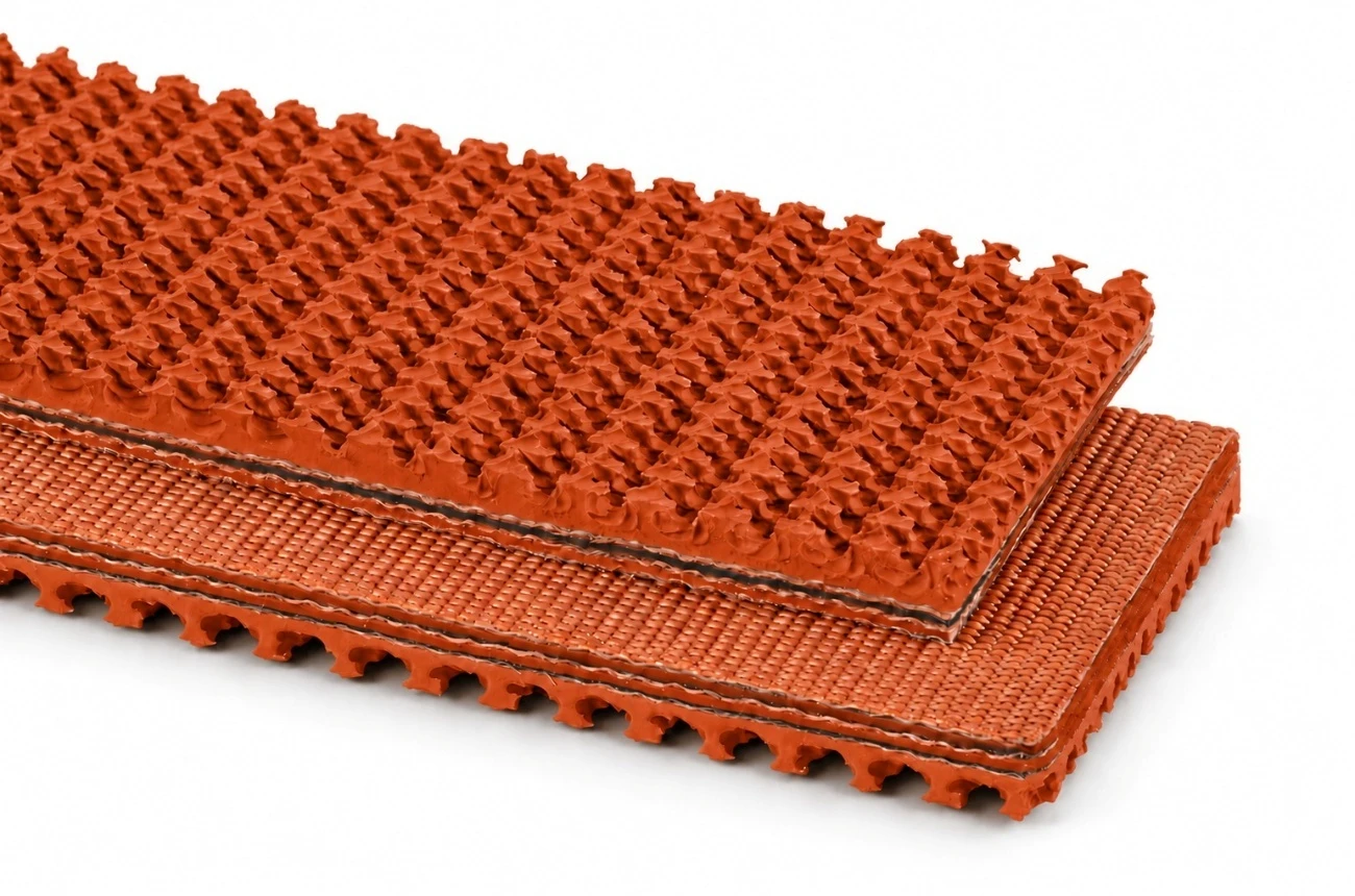
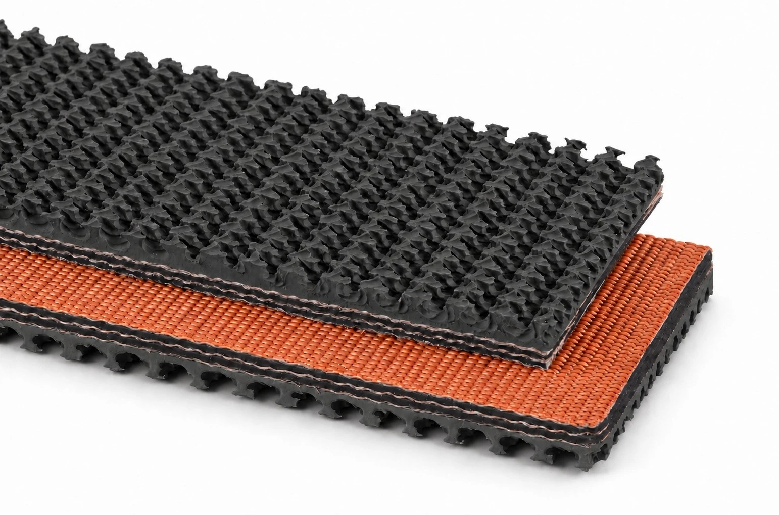
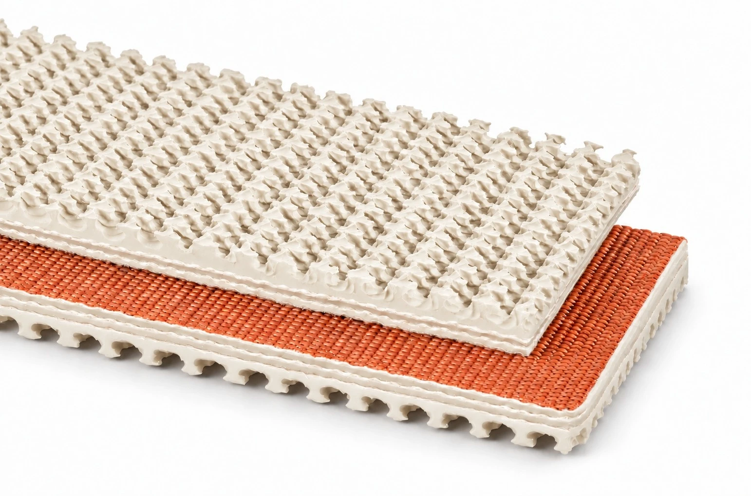
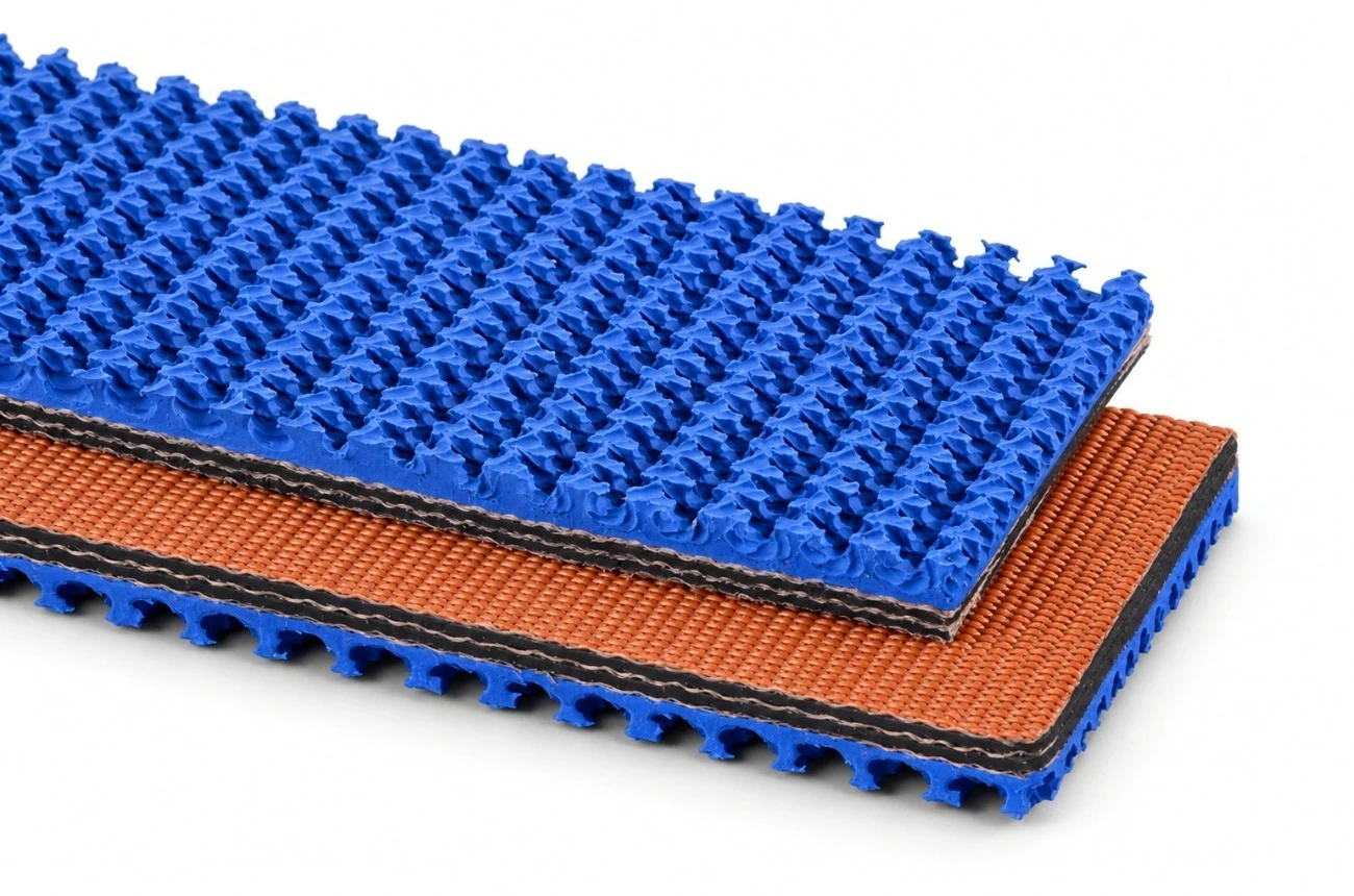

The rough top profile is formed to generate a large number of flexible contact points. This textured surface increases friction between the belt and the conveyed item, improving stability where the product is subject to incline, deceleration, acceleration or vibration.
Color selection is subject to the rubber compound, application, minimum production quantity and manufacturing availability. Color alone is not an indication of oil resistance, heat resistance, flame resistance, food suitability or antistatic performance. Any special property must be separately specified and technically confirmed.
| Configuration | Typical Selection Consideration |
|---|---|
| Black rough top | General industrial conveying and packaged goods |
| Tan rough top | Visual contrast and selected packaging/handling service |
| Blue rough top | Application differentiation and selected handling environments |
| Green rough top | Application differentiation and selected handling environments |
| Special color | Subject to compound feasibility, quantity and technical approval |
The following table defines a practical overall selection envelope for rough top rubber conveyor belts. Exact values depend on belt rating, carcass type, cover grade, overall thickness, pulley diameters and the manufacturing program.
| Parameter | Typical / Available Range |
|---|---|
| Belt width | Approx. 400–1,600 mm in the standard industrial range; wider constructions may be available on request |
| Ply count | Typically 2–4 plies; special constructions subject to design |
| Carcass | EP (Poliéster–Náilon) ou NN (Náilon–Náilon) |
| Common belt rating | Approx. 200–800 kN/m; higher/lower ratings subject to construction |
| Top cover | Rough top patterned rubber, typically from around 3 mm depending on profile and service |
| Bottom cover | Rubber-covered or bare back / fabric back |
| Overall thickness | Construction-dependent; commonly within approx. 6–12 mm for standard rough top unit-handling belts |
| Edge type | Cut edge or moulded edge |
| Roll length | Made to order, subject to belt thickness, width, roll diameter and transport limits |
| Splice | Hot-vulcanized, cold-bonded or mechanical, subject to carcass and application |
Since rough top belt selection is strongly application-dependent, the final specification must be based on conveyor geometry, belt speed, drive arrangement, pulley diameters, take-up, load type, unit weight, contact surface, operating temperature, contaminants and the required incline.
| Carcass Type | General Characteristics | Typical Use |
|---|---|---|
| EP (Polyester-Nylon) | High dimensional stability, good strength-to-weight ratio, relatively low longitudinal elongation | General-purpose rough top belts and inclined unit handling |
| NN (Nylon-Nylon) | High flexibility, good impact resistance and fatigue performance | Applications where flexibility and dynamic resistance are prioritized |
Carcass rating and ply count must be selected to provide adequate working tension while maintaining compatibility with the conveyor's pulley diameters. Excessive belt rating or excessive ply count can reduce flexibility and increase minimum pulley diameter requirements.
| Designation Example | Interpretation |
|---|---|
| EP 200/2 | EP textile carcass, nominal overall tensile rating of 200 kN/m, 2 plies |
| EP 315/3 | EP textile carcass, nominal overall tensile rating of 315 kN/m, 3 plies |
| EP 400/3 | EP textile carcass, nominal overall tensile rating of 400 kN/m, 3 plies |
| NN 400/3 | NN textile carcass, nominal overall tensile rating of 400 kN/m, 3 plies |
Designation conventions can vary by manufacturing standard. The approved technical data sheet and purchase order govern the belt supplied.
| Selection Item | Rubber-Covered Bottom | Bare Back / Fabric Back |
|---|---|---|
| Bottom surface | Borracha | Exposed fabric / treated fabric |
| Typical support | Idlers and pulleys | Slider bed and selected pulleys |
| Bottom-side friction | Conventional rubber contact | Lower slip resistance on suitable beds |
| Carcass protection | Higher environmental protection on the bottom side | Exposed textile surface; requires application compatibility |
| Selection priority | General conveyor service | Compact unit handling and slider-bed systems |
Bare-back belts should be applied only where the conveyor bed material, cleanliness, alignment and bottom-side wear conditions are suitable. Rubber-backed belts are generally preferred where the bottom side is exposed to contamination, impact or aggressive idler contact.
For both constructions, pulley diameter, transition geometry and take-up arrangement must be compatible with the selected carcass and belt thickness.
| Industry / Process | Typical Conveyed Product |
|---|---|
| Packaging & Distribution | Cardboard boxes, parcels, crates, packaged consumer goods |
| Bagging Plants | Paper bags, woven bags, polymer bags |
| Warehousing & Logistics | Unit loads and parcels on transfer or inclined conveyors |
| Airports & Terminals | Baggage handling |
| Paper & Cardboard Products | Cardboard boxes, paperboard parcels and converted paper products |
| Wood Products | Boards, panels and selected wood products |
| Glass & Fragile Products | Fragile packaged or supported units requiring cushioning |
| Industrial Assembly | Components and containers requiring stable transfer |
The belt is primarily intended for unit handling and packaged goods. When loose bulk materials are conveyed at steep angles, a chevron, cleated, sidewall or other special-purpose patterned belt may be more suitable.
Rough top belts are commonly used where smooth-surface belts exhibit material rollback or slippage. Industry references frequently indicate practical incline ranges of around 20° to 30° for many packaged-goods applications, with some installations reaching higher values under favorable conditions. The actual permitted angle must be established from the coefficient of friction, unit geometry, center of gravity, belt speed, vibration, acceleration and surface contamination.
| Factor | Effect on Permitted Incline |
|---|---|
| Dry, clean contact surface | Generally improves grip |
| Dust, oil, moisture or product fines | Can significantly reduce grip |
| Soft or conformable packaging base | Can increase contact area and stability |
| Rigid, smooth packaging base | Can reduce friction depending on material |
| Higher acceleration/deceleration | Can increase slippage tendency |
| High vibration | Can reduce load stability |
Standard rough top belts are generally specified with abrasion- and wear-resistant rubber suitable for unit handling. Special compounds can be engineered where the operating environment requires additional resistance; however, the rough top profile and the required special property must be mutually compatible.
| Compound Requirement | Application Note |
|---|---|
| Abrasion-resistant | For repeated contact and higher-wear conditions |
| Oil-resistant | For exposure to mineral oils, greases or oily products; the exact medium must be stated |
| Heat-resistant | For elevated-temperature conveyed products or ambient conditions; temperature profile required |
| Flame-resistant | For applications subject to specified fire-safety requirements |
| Cold resistance | For low-temperature environments requiring flexibility retention |
| Antistatic / conductive | Where electrical resistance limits are specified by the application or regulation |
Special properties are not assumed from belt color. Each requirement must be explicitly stated in the inquiry and supported by an agreed test standard or technical acceptance criterion.
Splice selection must preserve belt flexibility, tensile capacity and surface continuity, while fitting the conveyor's maintenance strategy. The preferred method depends on carcass construction, belt rating, pulley diameters, operating tension, required hygiene, downtime and equipment available on site.
| Method | General Use Consideration |
|---|---|
| Hot-vulcanized splice | Preferred for durable permanent joints, where vulcanization equipment and controlled procedures are available |
| Cold-bonded splice | Used in selected textile applications, subject to the adhesive system and service conditions |
| Mechanical fastener | Useful for quick installation or frequent belt removal; fastener type must be compatible with belt thickness and pulley diameter |
| Factory endless | Available for selected dimensions and transportable endless lengths |
Splicing procedures must be performed by qualified personnel, using materials compatible with the belt construction. Rough top surface preparation must avoid unnecessary damage to the profile outside the splice area.
| Inspection Item | Recommended Check |
|---|---|
| Tracking | Belt runs centered, without persistent edge contact |
| Surface profile | No abnormal flattening, tearing, chipping or contamination |
| Splices | No opening, lifting, fastener damage or localized cracking |
| Edges | No progressive fraying or carcass exposure |
| Bottom side | No abnormal glazing, abrasion or fabric damage |
| Pulleys / idlers | Clean, rotating freely and correctly aligned |
For accurate technical selection and quotation, please provide the following information:
| Required Data | Customer / Project Information |
|---|---|
| Conveyor type | Flat / inclined / declined / slider bed / idler-supported |
| Center Distance (m) | __________ m |
| Belt Width (mm) | __________ mm |
| Required belt length | __________ m |
| Incline angle | __________ graus |
| Belt Speed (m/s) | __________ m/s |
| Drive Pulley Diameter | __________ mm |
| Tail Pulley Diameter | __________ mm |
| Take-up type and travel | ____________________________ |
| Conveyed product | ____________________________ |
| Unit dimensions and weight | ____________________________ |
| Product contact surface | Paper / polymer / cardboard / wood / other |
| Operating Temperature | __________ °C |
| Contaminants | Dry / wet / dusty / oil / grease / chemical exposure |
| Preferred bottom side | Rubber-covered / bare back / to be recommended |
| Preferred color | Black / tan / blue / green / special |
| Splice Requirement | Hot / cold / mechanical / factory endless / to be recommended |
A complete purchase description must clearly identify the belt construction and intended service. The following format is recommended:
| Field | Example |
|---|---|
| Product | Rough Top Conveyor Belt (Patterned) |
| Carcass | EP 315/3 |
| Width | 1.000 mm |
| Top | Rough top patterned rubber |
| Bottom | Bare back / fabric back |
| Color | Black |
| Edge type | Cut edge |
| Length | 100 m roll |
| Splice | Open length for on-site hot splicing |
| Special requirement | Oil-resistant compound, if technically approved |
Designation example: ROUGH TOP – EP 315/3 – 1000 mm – BLACK – BARE BACK – CUT EDGE – 100 m.
All non-standard performance requirements, including oil resistance, heat resistance, flame resistance, antistatic properties or specific test standards, must be stated in the purchase specification.
Product supply may be specified against applicable customer requirements and recognized conveyor belt standards, subject to the selected construction and agreed manufacturing scope. Where required, inspection documentation may define dimensional checks, tensile properties, adhesion, cover properties and other agreed acceptance criteria.
| Document / Record | Purpose |
|---|---|
| Technical data sheet | Defines the ordered belt construction and rated characteristics |
| Dimensional inspection record | Confirms width, length and thickness, where specified |
| Physical properties test report | Reports the agreed rubber and/or carcass test parameters |
| Certificate of conformity | Confirms supply against the agreed purchase specification |
| Packing list / roll identification | Supports product logistics and traceability |
Final compliance must be based on the standards and acceptance criteria stated in the confirmed purchase order. Standard references must be matched to the actual belt category; requirements applicable to general rubber conveyor belts do not automatically define every special rough top profile.
| Attribute | Value |
|---|---|
| Brand | World Prime Services |
| Product Name | Rough Top Conveyor Belt (Patterned) |
| Category | Specialized Textile-Reinforced Rubber Conveyor Belt |
| Primary Function | High-grip conveying of packaged and unit loads on flat or inclined systems |
| Available Backing | Rubber-covered bottom or bare back / fabric back |
| Available Colors | Black, tan, blue, green and special colors subject to confirmation |
Factory-Continuous Rubber Belt for Reliable, Splice-Free Operation

World Prime Services Endless Conveyor Belt is supplied as a continuous, closed-loop rubber conveyor belt, eliminating the need for a field splice in the finished belt loop. This construction is intended for conveyor systems where reduced splice-related maintenance, smooth running, dimensional consistency and reliable continuous service are priorities.
Endless conveyor belts can be manufactured in EP or NN textile constructions and can be supplied with smooth, patterned, chevron or application-specific covers. Special compounds can be selected for abrasion, heat, oil, chemical, cold, antistatic or flame-retardant service.
| Engineering Objective | Operational Benefit |
|---|---|
| Factory-manufactured continuous loop | Eliminates a conventional field splice joint in the finished loop |
| Uniform carcass continuity | Supports smooth tracking and consistent load transfer |
| Controlled endless length | Improves fit and take-up setup |
| Application-specific cover compounds | Allows adaptation to wear, heat, oil, chemical or low-temperature service |
| Smooth or profiled surfaces | Supports horizontal or inclined conveying |
| Textile carcass options | Provides flexibility for light- to heavy-duty industrial service |
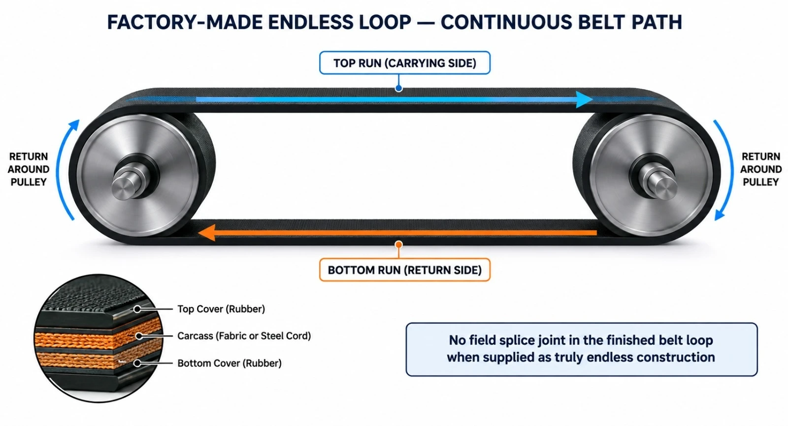
A true endless conveyor belt is manufactured or vulcanized as a closed loop to the specified net endless length. Because the belt is delivered as a continuous loop, installation requires access around the conveyor pulleys or a machine design that allows belt fitting without cutting.
For textile endless belts, net-length determination can be specified per ISO 16851:2012, which defines a method for determining the net length of a spliced endless textile conveyor belt. This standard does not apply to steel cord constructions.
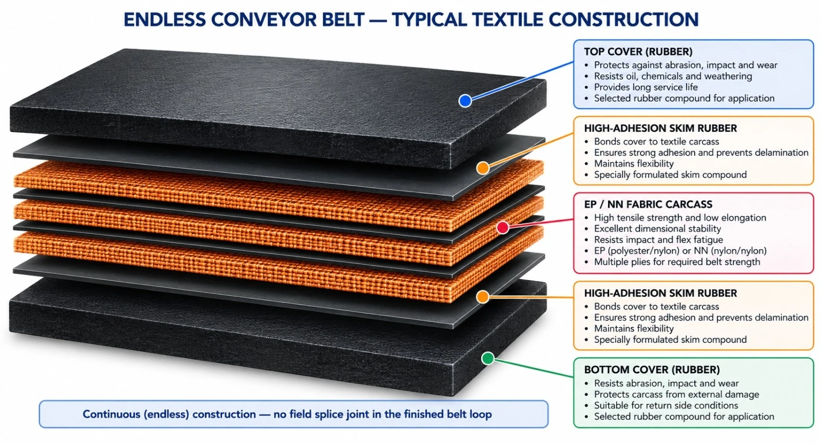
| Component | Engineering Function | Typical Options |
|---|---|---|
| Top cover | Primary conveying and wear surface | Smooth, abrasion-resistant, heat-resistant, oil-resistant, chemical-resistant or profiled |
| High-adhesion skim rubber | Bonds the cover to the carcass and transfers dynamic load | Application-specific adhesion system |
| Textile carcass | Carries the longitudinal operating tension | Polyester/nylon EP fabric or nylon NN fabric |
| Bottom cover | Protects the carcass on the pulley side | Standard or special-purpose rubber |
| Edges | Protects the belt sides and the reinforcement | Cut or moulded edge |
| Endless joint zone | Factory-controlled loop closure, where applicable | Vulcanized endless construction |
| Series | Description |
|---|---|
| EL-EP | EP Fabric Endless Conveyor Belt — low-elongation polyester/nylon construction for general and heavy-duty endless applications. |
| EL-NN | Nylon Fabric Endless Conveyor Belt — flexible construction for applications requiring impact tolerance and repeated flexing at the pulleys. |
| EL-AR | Abrasion-Resistant Endless Belt — heavy-duty cover compound for minerals, aggregates, recycling and bulk industrial material. |
| EL-CH | Chevron / Profiled Endless Belt — continuous endless belt with moulded profiles for inclined conveying. |
| EL-SP | Special-Compound Endless Belt — dedicated engineered endless construction for heat, oil, chemical, cold, antistatic or flame-retardant applications. |
| Carcass | Characteristics | Typical Use | Selection Consideration |
|---|---|---|---|
| EP Fabric | Low elongation, good dimensional stability and adhesion | General and heavy-duty industrial endless belts | Preferred where length stability matters |
| NN Fabric | High flexibility and good impact absorption | Shorter conveyors and repeated-flex service | Higher elongation than EP |
| High-Strength EP | Higher tensile capacity with low elongation | Heavy bulk material and longer endless loops | Requires appropriate pulley diameter |
| Special Reinforced Textile | Application-specific architecture | Severe-impact or tear-resistant applications | Project-specific design |
| Cover Family | Primary Duty | Typical Application |
|---|---|---|
| EL-GP | General use | Packaging, process and light/medium industrial handling |
| EL-AR | Abrasion-resistant | Minerals, aggregates, quarry, recycling |
| EL-HR | Heat-resistant | Hot bulk materials |
| EL-OR | Oil-resistant | Oily products and hydrocarbon-contaminated materials |
| EL-CR | Chemical-resistant | Chemically aggressive bulk materials |
| EL-CRD | Cold-resistant | Sub-zero and refrigerated environments |
| EL-AS | Antistatic | Static-control applications |
| EL-FR | Flame-resistant | Selected regulated industrial environments |
| Parameter | Catalogue Option / Range | Remarks |
|---|---|---|
| Belt width | Approx. 200–2,200+ mm | Project-dependent |
| Net endless length | Manufactured per the approved conveyor circumference | Measured per the agreed method |
| Textile carcass | EP / NN multi-ply | Strength selected from conveyor tension |
| Tensile class | Project-specific textile strength classes | Based on operating load and safety factor |
| Top cover thickness | Typically 2–15+ mm | Selected by wear and application |
| Bottom cover thickness | Typically 1.5–8+ mm | Selected by pulley-side service |
| Surface | Smooth / rough top / patterned / chevron | Application-specific |
| Edges | Cut edge / moulded edge | Project-specific |
| Special compounds | Heat / oil / chemical / cold / antistatic / flame | Subject to technical compatibility |
Precise net endless length is essential, since the belt must fit the conveyor geometry and remain within the available take-up range. The purchase specification must define the required net length, the measurement method, the belt tension condition during measurement and the acceptable tolerance.
| Control Item | Purpose |
|---|---|
| Net endless length | Ensures correct fit to the conveyor |
| Width tolerance | Supports tracking and pulley alignment |
| Total thickness | Confirms compatibility with pulley and system design |
| Squareness / loop geometry | Supports smooth tracking |
| Cover thickness | Confirms mechanical protection |
| Carcass continuity | Maintains uniform tensile behavior around the loop |
Important: a truly endless belt can be more difficult to install on conveyors that cannot be opened or disassembled. Installation access must be assessed before ordering.
| Industry / Application | Typical Materials | Primary Requirement |
|---|---|---|
| Packaging & Manufacturing | Boxes, bags, components | Smooth, reliable continuous operation |
| Mining & Quarrying | Ore, aggregate, crushed material | Abrasion resistance and strength |
| Cement | Limestone, cement products | Wear resistance |
| Recycling | Processed industrial materials | Impact and abrasion resistance |
| Agriculture & Grain | Grain, seeds, bagged materials | Clean tracking and reliable endless operation |
| Mobile & Compact Conveyors | Various bulk materials | Easy continuous-loop operation where designed for endless fit |
| Inclined Conveying | Granular and packaged materials | Chevron / profiled endless construction |

| Design Factor | Engineering Impact |
|---|---|
| Minimum pulley diameter | Controls carcass flex fatigue |
| Take-up range | Must accommodate belt fit and operating elongation |
| Pulley alignment | Critical for endless belt tracking |
| Drive traction | Depends on belt tension and pulley lagging |
| Belt speed | Influences dynamic load and cover wear |
| Conveyor access | Determines whether a closed-loop belt can be installed without cutting |
| Inspection Point | What to Check | Recommended Action |
|---|---|---|
| Covers | Cuts, abrasion, cracking or contamination | Repair before carcass exposure |
| Edges | Fraying, delamination or tracking damage | Correct alignment and repair |
| Loop closure / joint zone | Surface separation or localized fatigue, where applicable | Inspect and repair per the approved procedure |
| Pulleys | Lagging wear or buildup | Clean and maintain traction |
| Take-up system | Insufficient travel or excessive tension | Restore correct tension |
| Carcass | Exposed textile reinforcement | Immediate repair or replacement |
| Control Item | Purpose | Typical Stage |
|---|---|---|
| Net endless length | Confirm fit to the conveyor | Final inspection |
| Width / thickness | Confirm dimensional compliance | Final inspection |
| Carcass verification | Confirm EP/NN construction | Production |
| Full-thickness tensile test | Verify tensile performance | Laboratory |
| Elongation test | Verify deformation behavior | Laboratory |
| Adhesion test | Confirm cover-to-carcass bonding | Laboratory |
| Visual inspection / traceability | Detect defects and identify the manufacturing batch | Final inspection / dispatch |
| Reference | Relevance |
|---|---|
| ISO 16851:2012 | Determination of the net length of a spliced endless textile conveyor belt |
| ISO 14890:2026 | Rubber- or plastics-covered textile conveyor belts for general use |
| ISO 283:2023 | Full-thickness tensile strength and elongation test method for textile conveyor belts |
ISO 16851 applies to endless textile conveyor belts and excludes steel cord constructions. The final belt construction and acceptance criteria must be defined in the approved purchase specification.
| Project / Site | |
| Industry | |
| Conveyed Material | |
| Belt Width (mm) | |
| Required Net Endless Length (mm) | |
| Length Measurement Method | |
| Take-Up Range (mm) | |
| Pulley Center Distance (mm) | |
| Drive Pulley Diameter | |
| Tail Pulley Diameter | |
| Belt Speed (m/s) | |
| Capacity (t/h) | |
| Required Carcass Type | |
| Required Belt Strength | |
| Top / Bottom Cover (mm) | |
| Surface: Smooth / Rough / Patterned / Chevron | |
| Edge Type | |
| Abrasion Resistance Required? | |
| Heat Resistance Required? | |
| Oil Resistance Requirement | |
| Chemical Resistance Required? | |
| Cold Resistance Required? | |
| Antistatic Requirement | |
| Flame Resistance Requirement | |
| Applicable Standard | |
| Additional Operating Notes |
Enclosed Rubber Conveyor Belting for Environmentally Controlled, Curved and Long-Distance Bulk Material Transport

World Prime Services Pipe Conveyor Belt is designed to transform from a conventional flat belt at the loading and discharge zones into an enclosed tubular cross-section along the conveying route. The overlapping belt edges encapsulate the conveyed material, reducing spillage, dust dispersion and external contamination.
The construction is engineered to combine longitudinal tensile strength with controlled transverse flexibility and sufficient restoring force to maintain stable pipe formation through multi-roll idler stations.

| Design Objective | Operational Benefit |
|---|---|
| Enclosed transport | Reduces dust emission, spillage and material exposure |
| Pipe-forming flexibility | Allows belt closure around conveyed bulk |
| Curved routing capability | Supports complex horizontal and vertical alignment |
| Compact conveyor corridor | Can reduce transfer points and land requirements |
| Two-way environmental isolation | Protects surroundings from material and material from surroundings |
At the loading zone the belt runs in an open trough configuration. After loading, transition idlers progressively wrap the belt into a pipe, with the belt edges overlapping above the material. The closed belt is supported by multiple idlers arranged around the circumference. Before discharge, the belt is progressively opened and flattened.


| Component | Function | Engineering Requirement |
|---|---|---|
| Top cover | Material-side and environmental wear protection | Selected for abrasion, oil, heat or chemical exposure |
| Adhesion Rubber | Bonding and load transfer | High adhesion and fatigue resistance |
| Carcass | Longitudinal tensile load capacity | EP/NN fabric or steel cord |
| Transverse Reinforcement | Supports the tubular shape and overlap stability | Construction-specific |
| Bottom Cover | Idler-side protection | Wear and flex-fatigue resistance |
| Belt Edges | Create the overlap seal in the tubular shape | Dimensional stability and flexibility |
Fabric Pipe Conveyor Belt uses textile reinforcement, typically EP or NN construction, combined with high-elasticity and abrasion-resistant rubber compounds. It is suited to applications requiring flexible pipe formation and moderate-to-high operating tension.

| Carcass Option | Primary Characteristic | Typical Duty |
|---|---|---|
| EP Fabric | Low longitudinal elongation and dimensional stability | General industrial pipe conveyors |
| NN Fabric | High flexibility and impact absorption | Impact-oriented or shorter systems |
| High-Strength EP Multi-Ply | Higher tensile capacity | Longer and higher-load applications |
Steel Cord Pipe Conveyor Belt uses longitudinal steel cords as the primary tensile member and specially engineered rubber and transverse reinforcement to provide the flexibility required for pipe formation. It is intended for high-strength, long-distance and high-capacity systems.
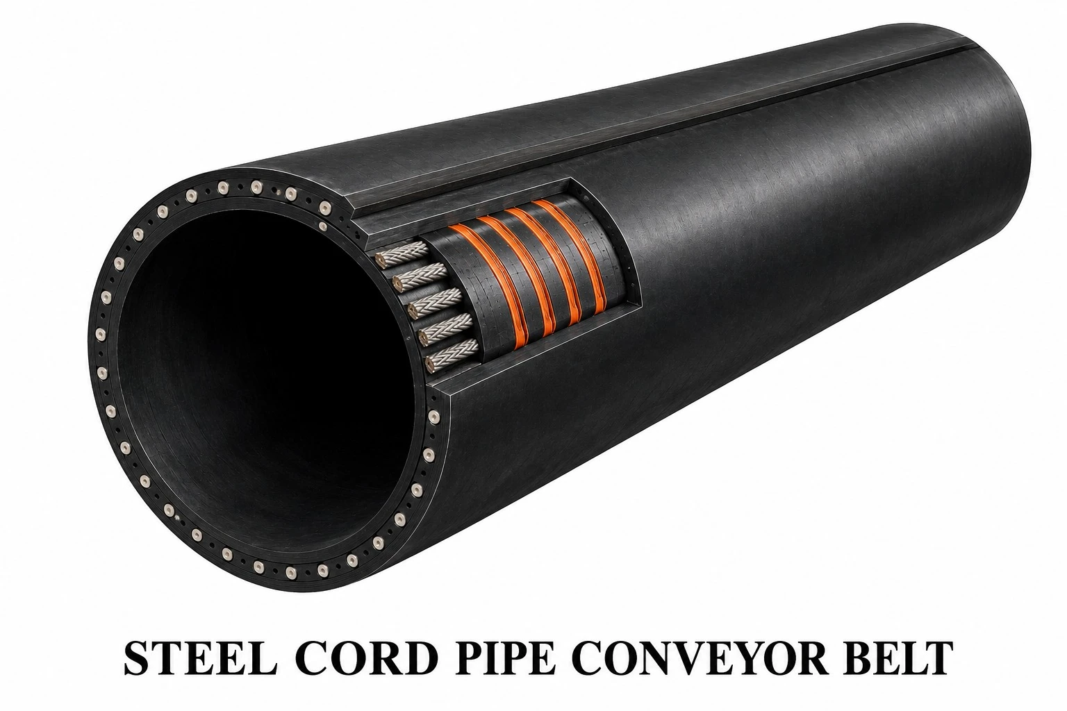
| Characteristics | Engineering Benefit |
|---|---|
| Tensile strength | Suitable for high operating tensions |
| Low elongation | Supports long-distance conveyor control |
| Steel cord carcass | High longitudinal load capacity |
| Engineered transverse flexibility | Allows repeated opening and closing of the tubular shape |
| Special cover compounds | Supports demanding bulk-material applications |
| Industry | Typical Materials | Pipe Belt Benefit |
|---|---|---|
| Mining | Ore, concentrates, coal | Long-distance contained conveying |
| Ports & Terminals | Coal, ore, concentrates, bulk commodities | Reduced spillage and dust |
| Power Generation | Coal, biomass, ash | Environmental containment |
| Cement | Clinker, limestone, raw materials | Curved closed routing |
| Metallurgy | Ore, coke and process materials | Protected bulk transfer |
| Chemical Industry | Selected compatible bulk chemicals | Reduced environmental exposure |
| Urban / Sensitive Areas | Dust-generating bulk materials | Compact enclosed conveying corridor |
| Cover Grade | Primary Property | Typical Application |
|---|---|---|
| Abrasion-Resistant | Wear resistance | Ore, coal, aggregate |
| Heat-Resistant | Resistance to elevated material temperature | Clinker and hot bulk |
| Oil-Resistant | Resistance to oils and fats | Oil-contaminated material |
| Cold-Resistant | Low-temperature flexibility | Cold climates |
| Chemical-Resistant | Resistance to selected corrosive exposure | Bulk chemical materials |
| Flame-Retardant | Reduced flame propagation | Specified fire-risk service |
| Antistatic | Controlled electrical resistance | Static-sensitive applications |
| Parameter | Required Project Data | Engineering Purpose |
|---|---|---|
| Pipe Diameter | Project-specific | Defines enclosed carrying section |
| Belt width | Matched to pipe diameter and overlap | Ensures stable closure |
| Capacity | t/h ou m³/h | Defines cross-section and speed |
| Belt Speed (m/s) | m/s | Capacity and dynamic behavior |
| Center Distance (m) | m | Tension and drive design |
| Horizontal Curves | Radius / geometry | Pipe stability and belt stress |
| Vertical Curves | Radius / geometry | Transition and tension control |
| Material Bulk Density | kg/m³ | Capacity calculation |
| Maximum Lump Size | mm | Pipe diameter and loading design |
| Moisture / Temperature | Operating range | Cover compound selection |
| Feature | Value |
|---|---|
| Fully enclosed conveying section | Improved environmental control |
| Reduced transfer points | Potential routing simplification |
| Horizontal and vertical curves | Greater layout flexibility |
| Weather protection | Reduced exposure to rain and wind |
| Reduced dust and spillage | Cleaner conveyor corridor |
| Compact route potential | Useful where conventional layouts are restricted |
The transition between flat, troughed and pipe form is a critical design area. Transition length, idler arrangement, overlap orientation and belt stiffness must be engineered to avoid excessive edge stress, buckling, twisting or loss of pipe shape.
| Design Item | Requirement |
|---|---|
| Transition Length | Matched to belt width, pipe diameter and stiffness |
| Overlap Position | Maintained consistently along the route |
| Idler Alignment | Precise multi-roll support geometry |
| Belt Rotation Control | Monitoring recommended on critical systems |
| Loading Centralization | Material centered before tubular closure |
Critical long-distance pipe conveyor systems may incorporate rip detection, steel-cord monitoring, splice monitoring and pipe-belt orientation or rotation monitoring. Monitoring strategy is selected according to carcass type, route complexity and operational criticality.
Hot-vulcanized splicing is normally preferred for high-duty pipe conveyor belts. The splice must reproduce longitudinal tensile performance while preserving transverse flexibility and uniform thickness to ensure stable passage through pipe-forming idlers.
| Splice Aspect | Requirement |
|---|---|
| Strength | Matched to belt rating |
| Flexibility | Compatible with repeated pipe formation |
| Thickness Uniformity | Avoid local stiffness discontinuity |
| Alignment | Prevent rotation and tracking instability |
| Inspection | Periodic visual and condition monitoring |
| Inspection Point | Condition to Monitor | Recommended Action |
|---|---|---|
| Belt Edges | Wear, cracking or overlap damage | Repair and investigate alignment |
| Covers | Abrasion, cuts and fatigue | Repair per the belt procedure |
| Splices | Separation or abnormal stiffness | Immediate engineering assessment |
| Idlers | Seizing, wear or misalignment | Replace / realign |
| Tubular Rotation | Persistent twist or overlap migration | Correct alignment and loading |
| Transitions | Buckling or edge stress | Review geometry and tension |
| Control Item | Verification |
|---|---|
| Belt Width / Thickness | Dimensional compliance |
| Carcass Construction | EP, NN or steel cord rating |
| Cover Physical Properties | Compound specification |
| Adhesion | Cover-to-carcass bonding |
| Transverse Stiffness | Suitability for tubular formation |
| Steel Cord Integrity | Cord arrangement and condition, where applicable |
| Visual Inspection | Surface and edge quality |
| Traceability | Production batch identification |
| Project / Site | |
| Industry | |
| Conveyed Material | |
| Bulk Density | |
| Moisture | |
| Material Temperature | |
| Maximum Lump Size | |
| Required Capacity (t/h) | |
| Pipe Diameter (mm) | |
| Belt Width (mm) | |
| Belt Speed (m/s) | |
| Center Distance (m) | |
| Lift / Descent (m) | |
| Horizontal Curve Data | |
| Vertical Curve Data | |
| Carcass Type (EP / NN / Steel Cord) | |
| Required Belt Rating | |
| Top Cover (mm) | |
| Bottom Cover (mm) | |
| Cover Compound | |
| Operating Ambient Temperature | |
| Required Safety Grade | |
| Splice Requirement | |
| Monitoring Requirement | |
| Applicable Standard / Customer Specification | |
| Additional Notes |
Pipe conveyor belt design is system-specific. Final belt width, pipe diameter, tensile rating, transverse stiffness, transition length, overlap behavior, cover grade and splice construction must be confirmed from the complete conveyor geometry and operating data.
The product catalogue intentionally presents the product under the World Prime Services name only and does not reproduce third-party brand names as product branding.

Minimum Drive Pulley Diameter from Carcass Thickness
Carcass Thickness, tc = ______ mm
Dmin = K × tc
Where: Dmin = Minimum Drive Pulley Diameter (mm); K = Carcass Material Factor; tc = Carcass Thickness (mm).
| Carcass Type | Material / Construction | K Factor | Calculation Formula | Minimum Drive Pulley Diameter |
|---|---|---|---|---|
| NN | Nylon / Nylon | 90 | Dmin = 90 × tc | ______ mm MINIMUM |
| EP | Polyester / Nylon | 108 | Dmin = 108 × tc | ______ mm MINIMUM |
| EE | Polyester / Polyester | 108 | Dmin = 108 × tc | ______ mm MINIMUM |
| ST | Steel Cord | 145 | Dmin = 145 × tc | ______ mm MINIMUM |
| Carcass Type | Example Carcass Thickness | Formula | Calculated Dmin |
|---|---|---|---|
| NN | 5,0 mm | 90 × 5,0 | 450 mm |
| EP | 5,0 mm | 108 × 5,0 | 540 mm |
| EE | 5,0 mm | 108 × 5,0 | 540 mm |
| ST | 5,0 mm | 145 × 5,0 | 725 mm |
Technical Note: the calculated value should be treated as a preliminary minimum pulley diameter, based on carcass thickness and the selected material factor. The final pulley diameter must also be verified against the belt manufacturer's recommendations, belt rating, carcass construction, splice type, belt tension, pulley function, wrap angle and applicable design or international standard requirements. For steel cord belts in particular, the approved belt technical data sheet and splice design must govern the final minimum pulley diameter.
Unit Conversion Formulas and Working Tension for Belt Strength
| Conversion | Formula | Conversion Factor |
|---|---|---|
| kgf/cm → PIW | PIW = (kgf/cm) × 5,5997 | 1 kgf/cm = 5,5997 PIW |
| PIW → kgf/cm | kgf/cm = PIW ÷ 5,5997 | 1 PIW = 0,17858 kgf/cm |
| PIW → N/mm | N/mm = PIW × 0,17513 | 1 PIW = 0,17513 N/mm |
| N/mm → PIW | PIW = (N/mm) × 5,71015 | 1 N/mm = 5,71015 PIW |
| kgf/cm → N/mm | N/mm = (kgf/cm) × 0,980665 | 1 kgf/cm = 0,980665 N/mm |
| N/mm → kgf/cm | kgf/cm = (N/mm) × 1,01972 | 1 N/mm = 1,01972 kgf/cm |
| Item | Input / Formula | Result |
|---|---|---|
| Input Belt Strength | ________ kgf/cm | |
| Convert kgf/cm to PIW | PIW = kgf/cm × 5,5997 | ________ PIW |
| Convert PIW to N/mm | N/mm = PIW × 0,17513 | ________ N/mm |
| Direct Conversion from kgf/cm to N/mm | N/mm = kgf/cm × 0,980665 | ________ N/mm |
| Input N/mm | ________ N/mm | |
| Convert N/mm to PIW | PIW = N/mm × 5,71015 | ________ PIW |
| Working Tension | ________ PIW | |
| Number of Plies | ________ CAMADAS |
When the belt rating is expressed as total PIW and a design safety factor (SF) is used:
Working Tension (PIW) = Nominal Belt Strength (PIW) ÷ Safety Factor (SF)
When the allowable working tension is already provided by the belt manufacturer, use the manufacturer's published working tension value, rather than recalculating it from the nominal breaking strength.
| Calculation | Formula | Purpose |
|---|---|---|
| Required Strength per Ply | PIW Necessário por Camada = PIW Total Necessário ÷ Número de Camadas | Determines the minimum nominal fabric strength required for each ply. |
| Total Belt Rating | PIW Total = PIW do Tecido por Camada × Número de Camadas | Calculates approximate total carcass rating from fabric rating and ply count. |
| Required Ply Number | Nº de CAMADAS = PIW Total Necessário ÷ PIW do Tecido por Camada | Round upward to the next whole ply, subject to manufacturer design limits. |
| Suggested EP Fabric | Select next standard EP fabric rating ≥ Required PIW per Ply | Selects an individual fabric type; the complete belt strength depends on the number of plies. |
| Parameter | Formula / Entry | Example Output Format |
|---|---|---|
| Required Total Belt Strength | Entrada = ______ PIW | e.g. 600 PIW |
| Nº de CAMADAS | Entrada = ______ | e.g. 4 PLY |
| Required Strength per Ply | PIW Total ÷ Nº de CAMADAS | 600 ÷ 4 = 150 PIW/camada |
| Suggested Fabric Type | Next available EP fabric ≥ required per-ply strength | Select from manufacturer's EP fabric range |
| Belt Type | Suggested EP Fabric / PLY No. | EP ___ / 4 |
Recommended general designation:
TIPO DE CORREIA = EP [CLASSIFICAÇÃO DO TECIDO] / [NÚMERO DE CAMADAS]
Important: an EP fabric designation identifies the selected carcass fabric specification according to the manufacturer's construction system. It should not automatically be assumed that the numeric EP designation multiplied by the ply count equals the finished belt's certified breaking strength unless that relationship is explicitly defined in the manufacturer's technical data.
| Input | Calculation | Result |
|---|---|---|
| 100 kgf/cm | 100 × 5,5997 | 559,97 PIW |
| 559,97 PIW | 559,97 × 0,17513 | ≈ 98,07 N/mm |
| 100 kgf/cm | 100 × 0,980665 | 98,0665 N/mm |
| 100 N/mm | 100 × 5,71015 | 571,015 PIW |
| Calculation | Excel Formula (Example Input Cell A2) |
|---|---|
| kgf/cm → PIW | =A2*5.5997 |
| PIW → N/mm | =A2*0.17513 |
| N/mm → PIW | =A2*5.71015 |
| kgf/cm → N/mm | =A2*0.980665 |
| Required Strength per Ply | =Total_PIW/PLY_No |
| Required Ply Number (Rounded Up) | =ROUNDUP(Required_Total_PIW/Fabric_PIW_Per_Ply,0) |
Technical Note: PIW means pounds per inch of belt width (lb/in) and N/mm means newtons per millimetre of belt width. These are force-per-unit-width quantities and are directly convertible. kgf/cm is also force per unit width. Final conveyor-belt selection must distinguish nominal breaking strength from allowable working tension and must follow the belt manufacturer's certified carcass rating, recommended safety factor, splice efficiency, pulley requirements and application conditions.
DIN • ISO • RMA/ARPM • AS • JIS • Special-Service Rubber Compounds
| Grade | Standard / Region | Properties | Breaking Strength (MPa, min.) | Elongation at Break (%, min.) | Abrasion (mm³, max.) | Typical Application |
|---|---|---|---|---|---|---|
| DIN W | DIN 22102 | Very high abrasion resistance; severe abrasive service. | 18 | 400 | 90 | Highly abrasive fines, ore, sand, sharp mineral products |
| DIN X | DIN 22102 | High tensile strength; strong resistance to cutting, gouging and impact. | 25 | 450 | 120 | Sharp rock, heavy ore, large lumps, severe-service mining |
| DIN Y | DIN 22102 | High-quality, general-purpose abrasion-resistant cover. | 20 | 400 | 150 | Ore, coal, limestone, aggregates, cement, general mining |
| DIN Z | DIN 22102 | Standard-service cover for moderately abrasive materials. | 15 | 350 | 250 | Less severe bulk handling, moderate abrasion |
| ISO H | ISO 14890 / legacy ISO 10247 classification | Heavy-duty service cover, emphasizing tensile strength and severe mechanical service. | 24 | 450 | 120 | Sharp, heavy and abrasive materials |
| ISO D | ISO 14890 / legacy ISO 10247 classification | High abrasion-resistance cover, with low volumetric wear. | 18 | 400 | 100 | Highly abrasive bulk materials |
| ISO L | ISO 14890 / legacy ISO 10247 classification | General-purpose cover for moderate abrasion. | 15 | 350 | 200 | General bulk material handling |
| RMA Grade I | Legacy RMA designation (USA) | Premium heavy-duty cover; high resistance to cutting, gouging and abrasion. | 17 | 400 | 150 | Sharp, abrasive materials, severe service |
| RMA Grade II | Legacy RMA designation (USA) | General-purpose abrasion-resistant cover. | 14 | 400 | 200 | Common abrasive bulk materials |
| ARPM Grade 1 | ARPM Heavyweight Conveyor Belt Guideline (USA) | High resistance to cutting, gouging and tearing, plus very good to excellent abrasion resistance. | 17 | 400 | 125 | Severe impact, sharp rock, heavy mining |
| ARPM Grade 2 | ARPM Heavyweight Conveyor Belt Guideline (USA) | Good to excellent abrasion resistance, with less emphasis on cutting/gouging than Grade 1. | 14 | 400 | 175 | General abrasive materials |
| AS A | AS 1332 | Very high abrasion resistance. | 17 | 400 | 70 | Extremely abrasive service |
| AS M | AS 1332 | Heavy-duty, high-strength cover. | 24 | 450 | 125 | Severe mining and heavy mechanical service |
| AS N | AS 1332 | General-purpose abrasion-resistant cover. | 17 | 400 | 200 | Normal abrasive bulk materials |
| JIS H | JIS industry cross-reference* | Heavy-duty, high-strength cover. | 24 | 450 | 120 | Severe mechanical service |
| JIS D | JIS industry cross-reference* | High abrasion-resistance cover. | 18 | 400 | 100 | Highly abrasive materials |
| JIS L | JIS industry cross-reference* | General-purpose cover. | 15 | 350 | 200 | Normal bulk material handling |
| JIS G | JIS industry cross-reference* | General-service cover found in industry comparison tables. | 14 | 400 | 250 | Moderate service |
| Resistance Type / Compound | Primary Resistance | Typical Standard / Reference | Key Performance Criterion | Typical Applications |
|---|---|---|---|---|
| Abrasion-Resistant (AR) | Resists surface wear caused by repeated slippage and contact with bulk material. | DIN W/Y/Z; ISO D/L; RMA/ARPM; AS; JIS | Abrasion loss, tensile strength, elongation; cutting/gouging performance may also be specified. | Ore, coal, sand, aggregates, cement raw materials |
| Super-Abrasion-Resistant (SAR) | Enhanced wear resistance for exceptionally abrasive service. | Usually manufacturer/project specification; may be compared to DIN W or AS A. | Very low abrasion loss; contractually agreed compound values. | High-silica ore, hard-rock fines, highly abrasive mineral products |
| Cut & Gouge Resistant | Resists cuts, chipping and deep mechanical damage caused by heavy, sharp lumps. | DIN X; ISO H; ARPM Grade 1; AS M are common reference grades. | High tensile strength and elongation, plus tear/cut/gouge resistance. | Sharp blasted rock, large ore lumps, scrap, severe-impact zones |
| Impact-Resistant | Absorbs impact energy and reduces cover/carcass damage. | Usually project-specific; often combined with a high-strength and breaker cover. | Dynamic impact, tear, puncture, adhesion and carcass protection. | Primary crushers, loading points, large-lump material |
| Tear-Resistant | Limits the propagation of longitudinal or transverse damage. | Belt-construction requirement; not defined by cover rubber alone. | Tear resistance, breaker reinforcement, steel/textile anti-tear systems. | Sharp foreign objects, retained material, severe mining |
| Heat-Resistant – Class 1 | Thermally aged rubber cover for moderate elevated temperature. | Historical ISO 4195 classification: Class 1, test exposure up to 100°C. | Change in hardness, tensile strength and elongation after thermal aging. | Warm clinker, foundry sand, moderate-temperature bulk solids |
| Heat-Resistant – Class 2 | Higher heat resistance than Class 1. | Historical ISO 4195 classification: Class 2, test exposure up to 125°C. | Retention of physical properties upon thermal aging. | Hot cement, coke, sinter, hot industrial material |
| Heat-Resistant – Class 3 | High heat resistance under the historical ISO classification. | Historical ISO 4195 classification: Class 3, test exposure up to 150°C. | Retention of hardness, tensile strength and elongation upon thermal aging. | Hot clinker, sinter and selected high-temperature solids |
| High / Extreme Heat-Resistant | Special EPDM/EPR or other heat-resistant formulation, for temperatures beyond common grades. | Manufacturer/project specification; verify actual continuous and peak material temperature separately from the ISO test class. | Thermal aging, cover cracking, hardening, adhesion retention. | Cement clinker, coke, foundry, steel and sintering applications |
| Oil-Resistant – MOR | Moderate oil resistance for materials with limited oil content. | Common industry/manufacturer designation; exact limits project-specific. | Volumetric swelling, tensile/elongation retention after oil exposure. | Recycling, fertilizer, wood products, oily materials |
| Oil-Resistant – OR | Standard/high resistance to mineral, animal or vegetable oils. | Manufacturer/project specification; test medium and exposure must be agreed. | Oil swelling, hardness and mechanical property retention. | Oily sand, metal parts, grain/oilseeds, industrial materials |
| Highly Oil-Resistant – HOR | Enhanced resistance for severe oil/grease exposure. | Manufacturer/project specification. | Low swelling and good retention after defined oil immersion. | High-oil-content materials and severely oily environments |
| Flame-Resistant | Reduces flame propagation when the ignition source is removed. | ISO 340:2022 for laboratory-scale flammability characteristics. | Flame duration/propagation performance per the applicable test. | Power plants, tunnels, enclosed or higher fire-risk surface conveyors |
| Fire-Resistant + Antistatic | Combines flame resistance with electrical conductivity to dissipate static charge. | ISO 340:2022 + ISO 284:2025; additional mine regulations may apply. | Flammability plus maximum electrical resistance. | Coal handling, explosive dust risk, selected mining applications |
| Underground Flame-Resistant | Engineered for underground mines under jurisdiction-specific safety requirements. | Applicable mining regulation plus ISO/EN/DIN or specified national standards. | Flame, drum friction, electrical resistance and possibly toxicity/smoke criteria. | Underground coal and mineral mines |
| Drum Friction Resistant | Reduces the tendency to generate dangerous heat, flame or incandescence when the belt slips against a driven drum. | ISO 20238:2018 | Heat, flame or incandescence behavior during drum-friction testing. | Fire-critical conveyor systems |
| Antistatic / Electrically Conductive | Dissipates electrostatic charge accumulated during belt operation. | ISO 284:2025 | Maximum electrical resistance per the standard/test requirement. | Dusty, dry or potentially explosive environments |
| Cold resistance | Maintains flexibility and crack resistance at low ambient/material temperatures. | Usually project/manufacturer specification; select based on minimum service temperature. | Low-temperature flexibility, brittleness/cracking resistance, dynamic performance. | Arctic mines, cold storage, outdoor winter conveying |
| Acid-Resistant | Resists degradation from acidic conveyed materials or chemical exposure. | Project/manufacturer specification; concentration and temperature must be defined. | Mass/volume change, tensile strength, elongation, hardness after chemical exposure. | Fertilizers, chemical plants, mineral processing |
| Alkali-Resistant | Resists alkaline materials and solutions. | Project/manufacturer specification. | Chemical aging and property retention. | Cement, lime, chemical processing |
| Acid & Alkali Resistant | Compound selected for combined chemical resistance. | Project/manufacturer specification. | Chemical compatibility depends on the medium, concentration and temperature. | Chemical processing and corrosive bulk handling |
| Ozone-Resistant | Resists cracking caused by ozone attack. | Rubber compound specification; relevant ozone test methods may be used. | Ozone crack resistance under defined strain/concentration. | Outdoor installations and ozone-rich environments |
| Weather / UV-Resistant | Improves resistance to sunlight, oxidation and outdoor aging. | Project/manufacturer specification. | Retention of properties under accelerated aging/weathering. | Outdoor overland conveyors, ports, stockyards |
| Low Rolling Resistance (LRR) | Reduces indentation rolling losses on the pulley-side cover. | ISO 23586:2022 provides width-related indentation rolling resistance test requirements. | Indentation rolling resistance; energy performance. | Long, high-power overland conveyor systems |
| Energy Saving / XLLR | Advanced low-hysteresis bottom cover compounds, for reduced power demand. | Manufacturer/project specification; may be assessed with ISO 23586 methods. | Dynamic loss / rolling resistance and temperature-dependent performance. | Very long overland conveyors and high-energy installations |
| High Friction | Provides an increased coefficient of friction where traction or incline requires it. | Project/manufacturer specification. | Coefficient of friction, wear and heat buildup. | Inclined conveyors, special drive/contact requirements |
| Low Friction | Reduces slippage drag in selected belt/support arrangements. | Project/manufacturer specification. | Coefficient of friction and wear. | Slider beds and special conveyor designs |
| Food Grade | Rubber/polymer cover formulated for food contact, where applicable. | Applicable food-contact regulation depends on market and material. | Migration/contact compliance plus mechanical properties. | Food, grain and packaged food handling |
| Non-Toxic / Hygienic | Special compound for applications requiring controlled composition and cleanliness. | Application-specific regulation/specification. | Chemical composition and migration requirements. | Food, pharmaceutical or special industrial handling |
| Heat Grade / Reference | Temperature Reference | Resistance Level | Typical Materials | Engineering Note |
|---|---|---|---|---|
| Class 1 / T1-type reference | Test class/laboratory reference of approx. 100°C | Moderate heat | Warm clinker, foundry sand, moderately hot bulk solids | Confirm actual material temperature, belt surface temperature and peak exposure. |
| Class 2 / T2-type reference | Test class/laboratory reference of approx. 125°C | Medium-high heat | Hot cement, coke, industrial solids | Thermal aging and adhesion are critical. |
| Class 3 / T3-type reference | Test class/laboratory reference of approx. 150°C | High heat | Clinker, sinter, hot industrial bulk material | Use ISO 4195 requirements/approach when contractually applicable. |
| Extreme heat compound | Project-specific; may exceed standard classes | Very high heat / intermittent peak | Incandescent or very hot clinker/sinter applications | Requires dedicated compound and application engineering; temperature claims are manufacturer-specific. |
| Safety Property | Standard / Reference | What It Evaluates | Selection Note |
|---|---|---|---|
| Flame-Retardant | ISO 340:2022 | Laboratory-scale flammability characteristics; limits flame persistence/propagation. | Specify where surface conveyor fire risk exists. |
| Antistatic / Conductive | ISO 284:2025 | Defines the maximum electrical resistance and corresponding test method, to prevent static-charge buildup. | Often combined with flame-resistant compounds. |
| Drum Friction | ISO 20238:2018 | Assesses the propensity to generate heat, flame or incandescence when a stalled belt contacts a rotating steel drum. | Important in fire-risk and mining service. |
| Underground Safety | Applicable national mining regulation + ISO/EN/DIN requirements | May combine flame, antistatic, drum friction and other safety criteria. | Must be specified according to the jurisdiction and mining authority. |
| Material / Duty | Primary Rubber Resistance | Typical Grade / Reference | Additional Engineering Consideration |
|---|---|---|---|
| Iron Ore / Copper Ore / Hard Rock | High abrasion + cutting/gouging + impact | DIN X, DIN W, ISO H/D, ARPM Grade 1, AS M/A | Consider steel/textile breaker for large sharp lumps. |
| Coal | Abrasion + flame/antistatic when required | DIN Y / ISO L-D mais ISO 340 e ISO 284 quando especificado | Underground use requires jurisdiction-specific fire-safety approval. |
| Cement / Limestone | Abrasion; heat if material is hot | DIN Y/W, ISO D/L; ISO 4195 para cobertura resistente ao calor | Clinker normally requires a dedicated heat-resistant compound. |
| Clinker / Sinter / Coke | Heat + abrasion | Heat-resistant compound + abrasion specification | Define the continuous and peak temperatures. |
| Aggregates / Quarry Rock | Abrasion + cutting/gouging | DIN X/Y/W, ISO H/D, ARPM Grade 1/2 | Lump size and loading height affect the required cover thickness. |
| Oily Material / Recycling | Oil resistance + abrasion | Project-specific MOR / OR / HOR | Define the oil type, concentration and exposure duration. |
| Fertilizer / Chemicals | Chemical + oil/acid/alkali as relevant | Project-specific chemical-resistant compound | Provide the exact chemical composition, concentration and temperature. |
| Long-Distance Overland | Abrasion + low rolling resistance | Application cover grade + ISO 23586 assessment | The bottom cover compound can materially affect energy demand. |
| Cold-Climate Mining | Cold + abrasion/cutting | Cold-resistant compound combined with the required wear grade | Specify the minimum ambient and starting temperature. |
| Ports / Terminals | Weathering/ozone + abrasion | Outdoor aging-resistant compound with the required wear grade | Salt, UV, moisture and long storage periods must be considered. |
| Property | Typical Unit | Purpose / Specification Note |
|---|---|---|
| Tensile strength | MPa | Minimum value according to the selected cover class or project specification. |
| Elongation at break | % | Minimum value according to the selected cover class. |
| Abrasion Loss | mm³ | Maximum permitted volume loss; a lower value generally indicates better laboratory abrasion resistance. |
| Tear Resistance | N/mm or specified method | Important for sharp materials and cutting/gouging service. |
| Hardness | Shore A / IRHD | Controls deformation, wear response and in-service behavior. |
| Cover-to-Carcass Adhesion | N/mm | Critical for preventing delamination. |
| Thermal Aging Retention | % change | Required for heat-resistant covers; changes in tensile strength, elongation and hardness must be controlled. |
| Oil Swelling / Property Retention | % change | Required for oil-resistant grades; the test oil and exposure conditions must be defined. |
| Electrical resistance | Ω | For antistatic/conductive belts, per the applicable standard. |
| Flammability | Time / test result | For flame-resistant grades, per the applicable standard. |
| Indentation Rolling Resistance | Width-related test result/output | For low-rolling-resistance, energy-efficient overland belt designs. |
| Ozone / Weather Resistance | Test-specific result | For outdoor aging and crack resistance, when specified. |