Full catalog, 27 pages — browse the index or scroll the page.
World Prime Services supplies industrial solutions for machine tool accessories, chip conveyor systems, coolant filtration equipment and customized automation products for CNC machining, metalworking and heavy industry. Our portfolio is designed to provide high reliability, robust construction and long service life, supporting customers with engineering expertise, technical consulting and global sourcing. Our product range includes hinged belt chip conveyors, scraper conveyors, magnetic chip conveyors, screw conveyors, vibrating conveyors, paper band filters, coolant management equipment and related accessories. Each solution can be customized to meet machine dimensions, chip characteristics and production requirements.
Hinged steel chain assemblies for chip handling and machine-tool conveyor systems
A modular range of steel hinged chains designed for continuous transport of metal chips, swarf, scrap and small components. Chain geometry, plate material, perforation pattern, side wings and belt width can be configured to match the chip type, coolant content and conveyor duty.

| Pitch | Typical Shaft Ø | Typical Roller Ø | Plate Thickness | Recommended Duty |
|---|---|---|---|---|
| 31,75 mm | Ø8 mm | Ø19,05 mm | 1,0 / 1,5 / 2,0 mm | Compact machine tools |
| 38,10 mm | Ø8 mm | Ø22,23 mm | 1,0 / 1,5 / 2,0 mm | Light to medium duty |
| 50,80 mm | Ø10 mm | Ø28,58 mm | 1,0 / 1,5 / 2,0 / 3,0 mm | General industrial duty |
| 63,50 mm | Ø10 mm | Ø40 mm | 1,5 / 2,0 / 3,0 mm | Medium-heavy chips |
| 76,20 mm | Ø14 mm | Ø44,45 mm | 1,5 / 2,0 / 2,5 mm | Heavy-duty conveying |
| 101,60 mm | Ø14 mm | Ø57,15 mm | 2,5 / 3,0 / 4,0 mm | Large chips and parts |
Reference geometries for standard conveyor-chain pitches
The following drawings illustrate representative chain and plate geometries. Final dimensions, belt width, plate profile and side-wing construction are confirmed for each conveyor application.

Efficient handling of fine chips, short swarf and sediment-bearing coolant
The scraper conveyor uses crossbars or scraper paddles attached to a driven chain to collect and drag chips along the conveyor floor toward the discharge point. It is particularly suitable for fine metallic chips, small fragments and applications where coolant recovery is required.


| Parameter | Standard Configuration | Available Options |
|---|---|---|
| Drive motor | 0.20 kW geared motor, 220/380 V | Alternative voltage, power and ratio |
| Chain pitch | 31,75 mm reference configuration | Other pitches for custom duty |
| Scraper width | 150-600 mm, typically in 50 mm increments | Special width to suit machine interface |
| Scraper arrangement | One scraper per six chain pitches | Custom spacing and wiper profile |
| Conveyor speed | 1,2–1,4 m/min, 50/60 Hz | Fixed or variable speed |
| Incline angle | 60° reference configuration | Custom angle and discharge height |
| Safety | Torque limiter / overload protection | Emergency stop, CE-style guarding, jam sensor |
Automatic transport of long, curled, bundled and high-volume machining chips
The hinged belt conveyor is a proven solution for collecting and discharging ferrous and non-ferrous chips generated by CNC lathes, machining centers, milling machines and automated production equipment. The articulated steel belt provides positive conveying and may be configured with solid, perforated or embossed plates.


| Parameter | Standard Configuration | Available Options |
|---|---|---|
| Belt pitch | 31,75 / 38,10 / 50,80 / 63,50 / 76,20 / 101,60 mm | Selected according to chip load and belt width |
| Belt width | 150-2,000 mm available by design | Custom width and side-wing height |
| Drive | Geared motor, 220/380 V | Alternative voltage, speed and power |
| Conveyor speed | Typical 1.6-2.2 m/min | Variable-frequency control |
| Incline angle | 45° or 60° typical | Custom geometry and discharge height |
| Belt material | Carbon steel or stainless steel | Galvanized, perforated or reinforced plate |
| Protection | Torque limiter or current sensor | Jam detection, emergency stop, full guarding |
| Installation | Floor-mounted or machine-integrated | Pit-mounted, tank-mounted or mobile version |
Contact-free conveying of small ferrous chips, fines and short swarf
The magnetic chip conveyor is intended for ferrous-material applications that generate small chips and fines. Powerful magnets travel beneath a sealed, stationary stainless-steel surface, moving the collected material toward the discharge point without an exposed moving belt on the conveying face.


| Selection Item | Required Information |
|---|---|
| Chip material / geometry | Ferrous composition; fine, short, needle-like, powder or mixed chips |
| Capacity / coolant | Average and peak chip volume; coolant type, flow and return requirement |
| Machine interface | Inlet length, chute width, mounting position and available envelope |
| Discharge geometry | Height, incline angle and collection-bin position |
| Electrical / finish | Voltage, control, safety, paint color and stainless-steel grade |
Compact auger-type chip removal for confined machine-tool installations
The HRLX series uses a rotating screw flight inside a steel trough to transport short chips and granular machining residue from the collection point to the discharge outlet. The compact construction is suitable for installation beneath CNC machine tools where available space is limited.
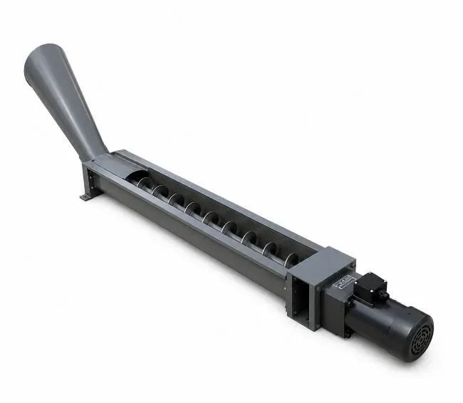

| Model | Screw Diameter (mm) | Outer Trough Width (mm) | Recommended Chip Size | Typical Application |
|---|---|---|---|---|
| HRLX-80 | 80 | 72 | Fine to short | Compact CNC lathes and machining centers |
| HRLX-100 | 100 | 100 | Short / granular | General machine-tool chip discharge |
| HRLX-120 | 120 | 122 | Medium chip volume | Higher-capacity machine bases |
Modular screw conveyor configurations for chip and scrap handling
The YSLX series provides a modular screw conveyor platform with multiple trough and screw-flight configurations. It is designed for conveying short chips, powder, small granules and fragmented scrap generated during machining and industrial processing.

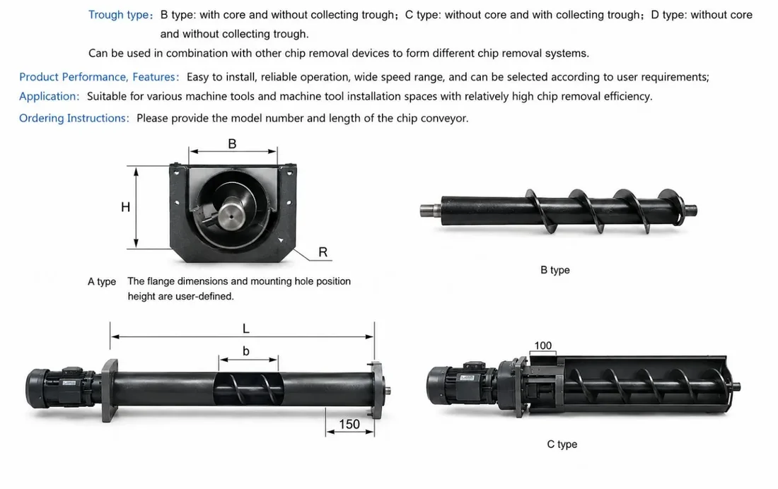
| Configuration | Construction | Best Suited For | Engineering Notes |
|---|---|---|---|
| Type A | Shafted screw / open trough | Short chips and dry scrap | Simple maintenance and direct discharge |
| Type B | Shafted screw / covered trough | Coolant-rich machining chips | Improved containment and operator protection |
| Type C | Shaftless screw | Irregular or entangling residue | Reduced obstruction around a center shaft |
| Type D | Custom multi-inlet system | Central collection networks | Engineered inlet spacing and drive torque |
Flexible sidewall belt conveyor for continuous material transfer
The skirt belt conveyor combines a durable belt with flexible corrugated sidewalls and transverse cleats to retain material during horizontal and inclined transport. It is suitable for chips, components, granules and bulk materials where product containment and clean transfer are required.

| Selection Parameter | Available Engineering Range |
|---|---|
| Conveyor arrangement | Horizontal, inclined, L-type, Z-type or custom |
| Belt construction | PVC, PU, rubber or application-specific belt |
| Sidewall / cleat design | Selected according to particle size, incline and capacity |
| Frame construction | Carbon steel, coated steel or stainless steel |
| Drive control | Fixed speed, variable frequency drive or machine interlock |
| Accessories | Hopper, cover, chute, guards, casters and sensors |
Dimensional values are confirmed according to the machine interface, transfer height, belt width, chip or product characteristics and required throughput. The final structure should be reviewed together with the discharge hopper, receiving container and service-access clearances.
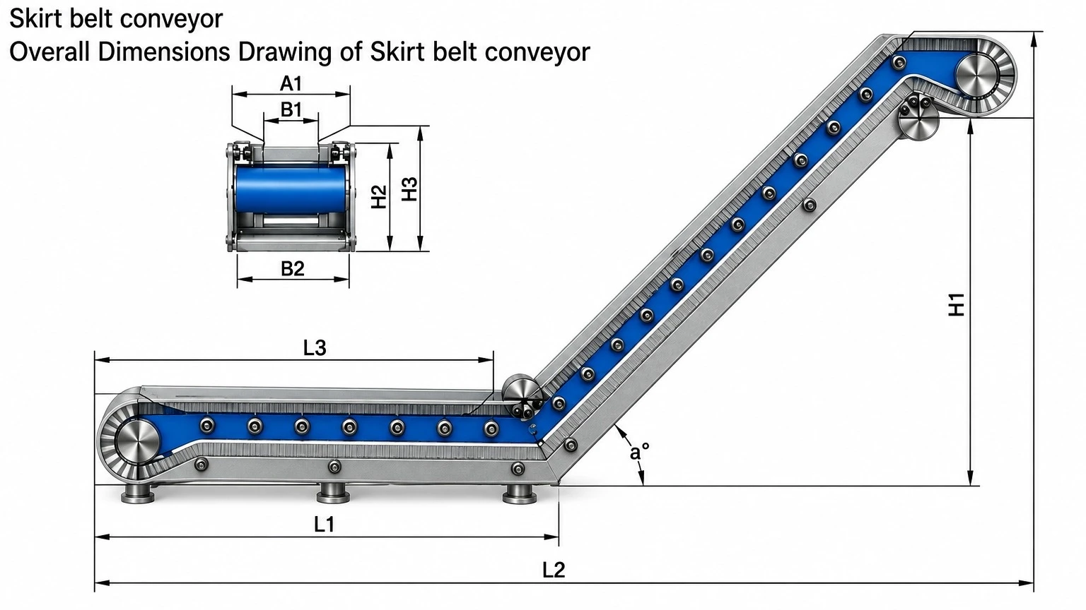
| Type | L1 | L2 | L3 | A1 | B1 | B2 | H1 | H2 | H3 | α |
|---|---|---|---|---|---|---|---|---|---|---|
| BZDBSSJ-100 | ≤5M | ≤L | ≤7M | ≥L | 180–550 | 300–1000 | — | 140 | ≥140 | 0–90° |
| BZDBSSJ-130 | ≤8M | ≤10M | 190 | ≥190 | ||||||
| BZDBSSJ-170 | ≤15M | ≤18M | 240 | ≥240 | ||||||
| BZDBSSJ-210 | ≤25M | ≤28M | 290 | ≥290 | ||||||
| BZDBSSJ-X | — | — | — | — |
Available cleat profiles: T type, C type and TC type.

| Application Condition | Recommended Design Consideration |
|---|---|
| Fine or granular material | Reduced side gaps and closely spaced cleats |
| Wet machining chips | Oil-resistant belt and drainage / coolant-return provisions |
| High incline angle | Higher cleats and corrugated sidewalls selected for load retention |
| Heavy components or scrap | Reinforced belt, impact zone and heavy-duty frame |
| Frequent washdown | Stainless-steel construction and sealed electrical components |
| Mobile operation | Locking casters, flexible power connection and guarded drive |
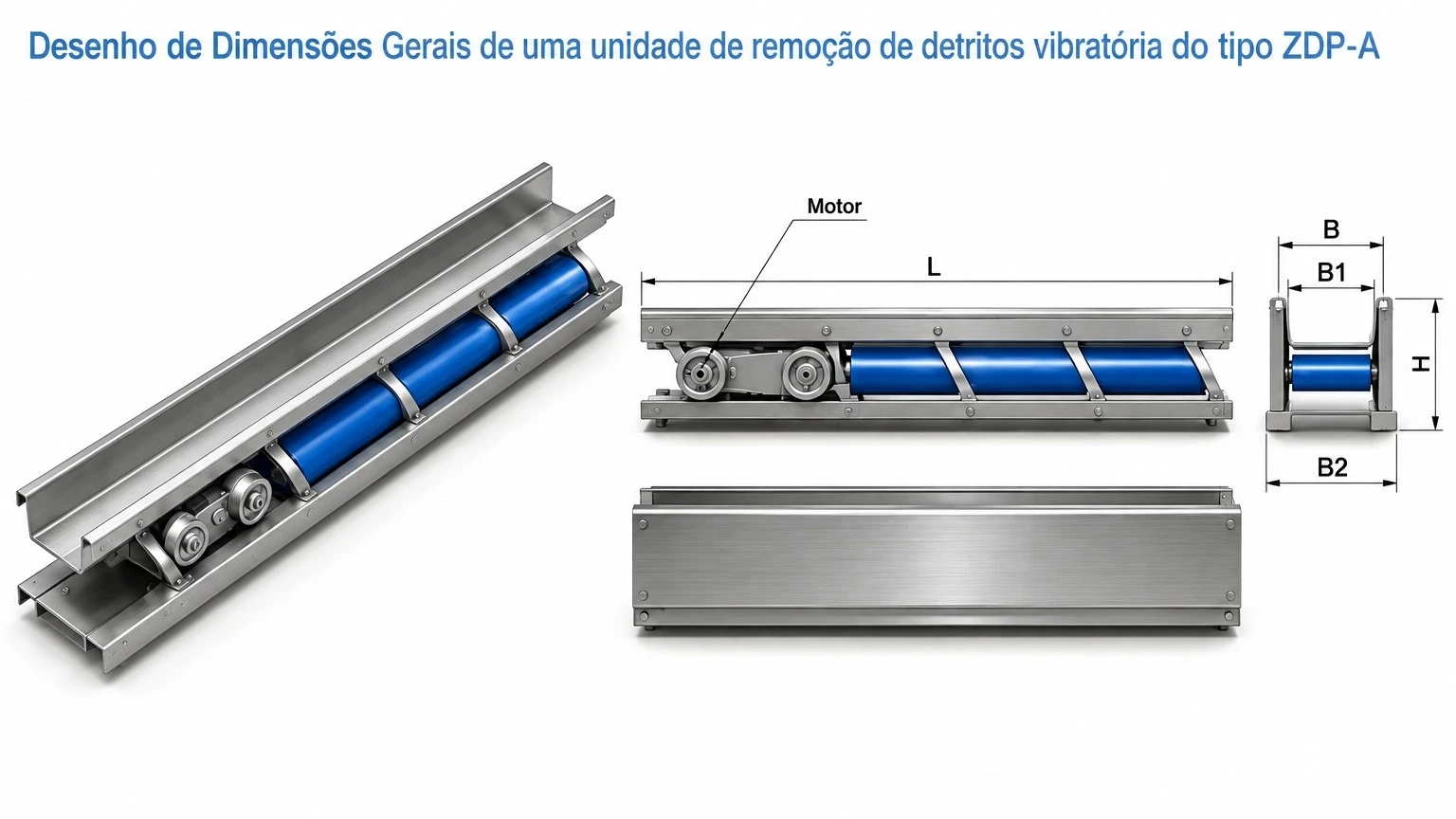
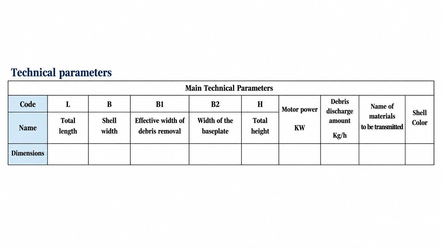
ZDP-A/B series — low-profile vibratory conveying for chips, fines and small parts
The ZDP-A/B plane vibrating chip conveyor transfers material through controlled linear vibration generated by an eccentric or vibration drive. With no circulating belt or chain in the conveying channel, the system provides a simple, low-profile solution for applications where chips must be moved over a straight path.
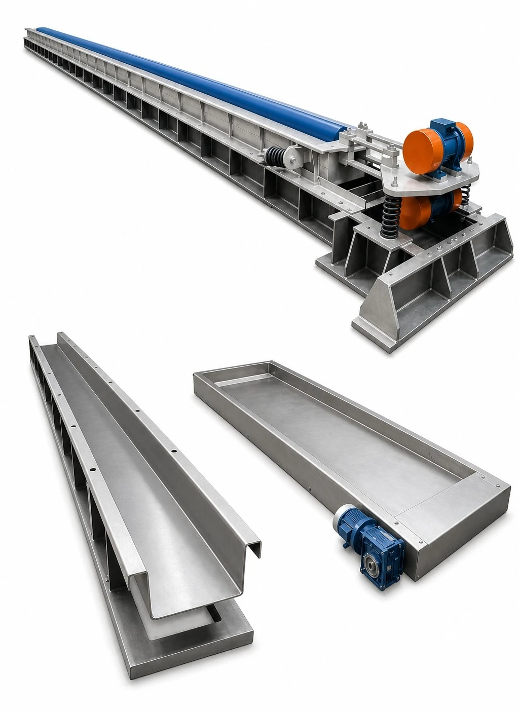
| Model Family | Drive Principle | Typical Installation | Main Advantage |
|---|---|---|---|
| ZDP-A | Eccentric vibration drive | Machine base or central channel | Simple construction and stable linear transfer |
| ZDP-B | Vibration motor drive | Stand-alone or integrated line | Flexible arrangement and compact installation |


| Engineering Item | Specification Basis |
|---|---|
| Conveyor width | Selected from chip volume, part size and machine opening |
| Conveyor length | Customized to machine footprint and discharge point |
| Inclination | Normally low-angle; engineered according to conveying test |
| Drive selection | Eccentric unit or vibration motor according to load and length |
| Material contact surface | Painted carbon steel, stainless steel or wear-resistant liner |
| Control | Independent panel, machine interlock, timer or variable control |
| Mounting | Isolated support, machine-mounted or floor-mounted structure |
Final capacity depends on material density, chip geometry, coolant content, vibration amplitude, frequency and conveying inclination. Application testing is recommended for unusual chip forms, sticky residue or mixed materials.
ZGA series — automatic gravity filtration for machine-tool coolant systems
The ZGA paper tape filter removes suspended solids from water-based or oil-based machine-tool coolant. Contaminated liquid passes through disposable filter media supported by a conveyor screen. As solids accumulate and flow resistance increases, the control system advances clean paper and discharges the contaminated media into a collection container.
This filter consists of several parts, including a paper tape, a speed reducer, a transmission mechanism, a signaling mechanism, and a liquid pump. It utilizes the filtration effect of the paper tape to remove metallic and other non-metallic impurities from the coolant. This ensures the cleanliness of the cutting fluid, extending its service life by 10-20 times and improving the surface quality of machined parts. The paper tape filter achieves a filtration efficiency of 98%, can be automatically controlled, and is an ideal accessory for various types of grinding machines, honing machines, and other precision machining tools.

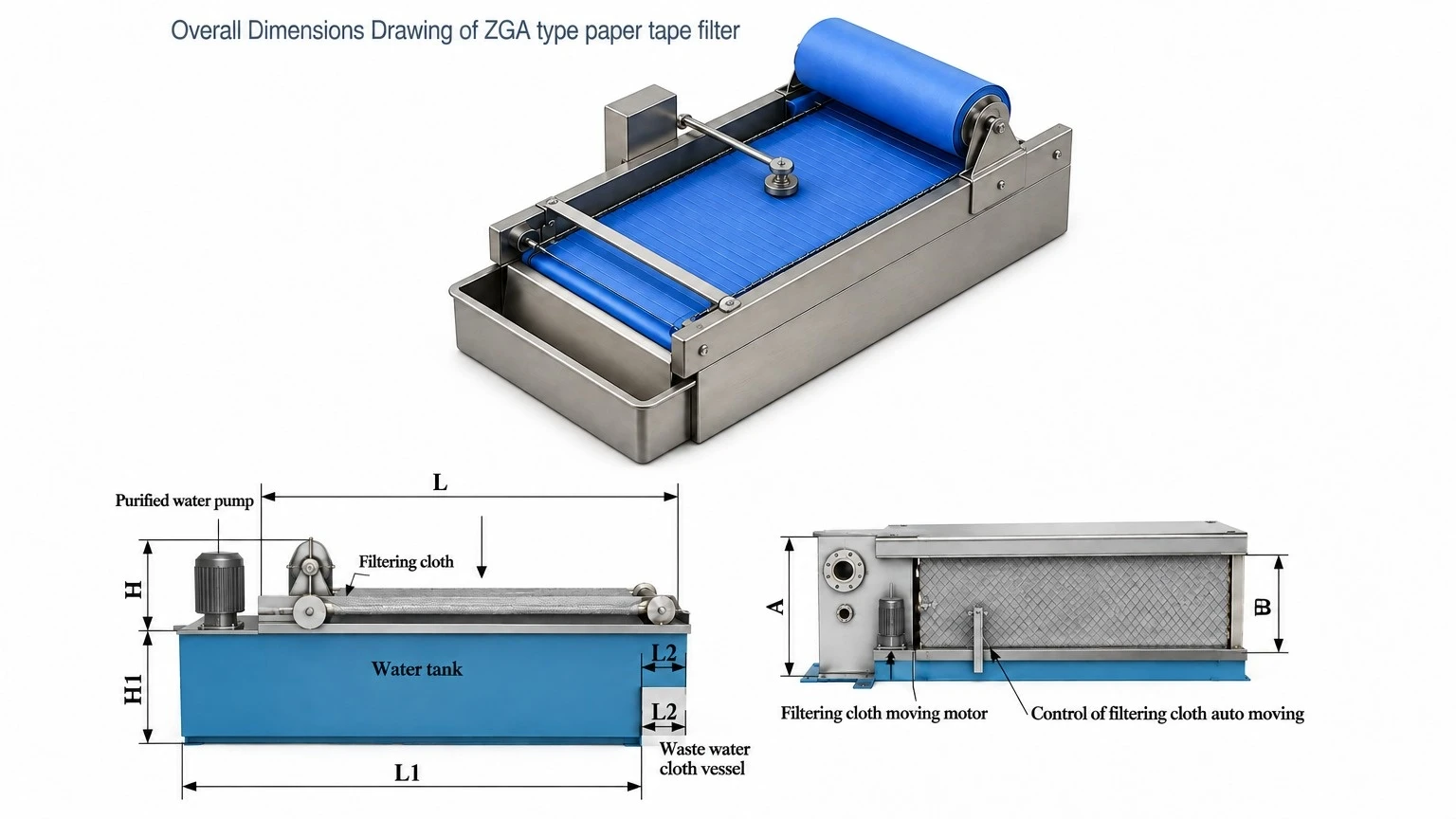
| Model | Flowrate (L/min) | Width | Width of the Filtering Cloth | Length of the Filter | Height of the Filter | Height of Water Tank H1 | Length of Water Tank L1 | Extended Length of the Filter L2 | Accuracy of Filtration |
|---|---|---|---|---|---|---|---|---|---|
| ZGA-25 | 25 | 400 | 320 | 800 | 350 | ≥200 | ≤1000 | 100 | 3,5–5 |
| ZGA-50 | 50 | 600 | 520 | 800 | 350 | ≤1000 | 100 | ||
| ZGA-75 | 75 | 600 | 520 | 1000 | 350 | ≤1300 | 100 | ||
| ZGA-100 | 100 | 800 | 720 | 1200 | 350 | ≤1500 | 100 | ||
| ZGA-150 | 150 | 800 | 720 | 1500 | 350 | ≤1800 | 100 | ||
| ZGA-200 | 200 | 1100 | 1000 | 1500 | 400 | — | 150 | ||
| ZGA-250 | 250 | 1100 | 1000 | 1800 | 400 | — | 150 | ||
| ZGA-300 | 300 | 1100 | 1000 | 2200 | 400 | — | 150 | ||
| ZGA-400 | 400 | 1100 | 1000 | 2500 | 400 | — | 150 | ||
| ZGA-500 | 500 | 1400 | 1200 | 2800 | 550 | — | 150 | ||
| ZGA-600 | 600 | 1400 | 1200 | 4000 | 550 | — | 150 | ||
| ZGA-800 | 800 | 1600 | 1500 | 3600 | 550 | — | 200 | ||
| ZGA-1000 | 1000 | 1600 | 1500 | 4500 | 550 | — | 200 | ||
| ZGA-1200 | 1200 | 2000 | 1800 | 4500 | 600 | — | 200 | ||
| ZGA-1500 | 1500 | 2000 | 1800 | 5500 | 600 | — | 200 |
Note: the water tank shape and size shall be determined according to the site conditions. If there is any requirement for the coolant temperature, a temperature control device can be installed on top of the water tank. This filter machine is automatically operated, without manual operation.
| Process Stage | Function |
|---|---|
| Coolant inlet | Distributes contaminated coolant across the filter area |
| Disposable filter paper | Captures fines and suspended machining residue |
| Support conveyor | Carries the filter media and accumulated sludge |
| Level control | Starts media advance when flow resistance raises coolant level |
| Clean tank outlet | Returns filtered coolant to the machine-tool system |
| Sludge discharge | Transfers used filter paper to the collection container |
| Customer / Project Information | |
|---|---|
| Coolant type | Water-based emulsion, synthetic coolant or oil |
| Required flow rate | L/min or m³/h at normal and peak machine demand |
| Contaminant material | Steel, cast iron, aluminum, abrasive or mixed material |
| Particle loading | Estimated solids concentration and chip/sludge volume |
| Required filtration | Nominal filter-paper grade or target cleanliness |
| Tank arrangement | Integrated reservoir, external tank or machine connection |
| Pump requirement | Supply pressure, return pressure and redundancy |
| Electrical standard | Voltage, frequency, control interface and safety requirement |
ZCB series — two-stage filtration for ferrous particles and fine coolant contamination
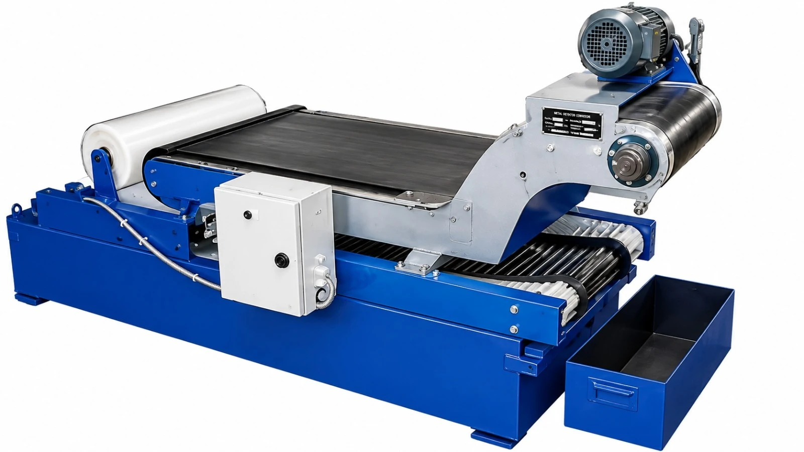
The ZCB magnetic roller paper tape filter combines magnetic pre-separation with disposable paper filtration. Ferrous particles are captured by the magnetic separator before the coolant reaches the filter media, reducing paper consumption and improving filtration stability. Remaining fines are retained by the paper tape before the clean coolant returns to the machine system.
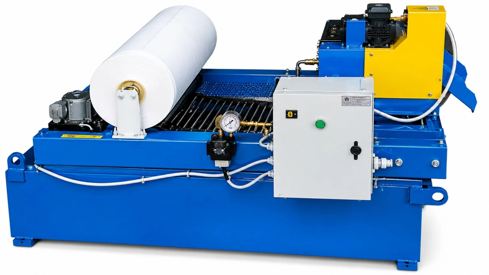
| System Module | Technical Function |
|---|---|
| Magnetic separator | Removes ferrous chips and particles from incoming coolant |
| Paper tape filter | Captures remaining fine and non-magnetic contamination |
| Drive and media control | Advances clean filter media according to liquid level or pressure condition |
| Coolant reservoir | Collects filtered liquid for recirculation |
| Pump group | Returns coolant to the machine at the specified flow and pressure |
| Electrical controls | Provides automatic operation, protection, alarms and interface signals |
System sizing must be based on coolant flow, contaminant loading, ferrous content, required cleanliness, available installation space and machine operating cycle.